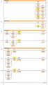
The hardwired circuit shown can be programmed to show how contacts of a programmed output relay can be examined for an ON or OFF condition as many times as you like. I can not get my solenoid and pilot light to turn on located in problem 1 of the ladder logic picture.
What states are CR1, CR2, CR3 and CR4 in when the button is pushed? OPEN or CLOSED? I am assuming all 4relay contacts are being driven by coil CR as in the attached file.
That is because as soon as the rung is energized via T1 or PB1 the solenoid will turn off.
BTW, you do not label CR contacts as CR1, CR2, CR3 etc, as they would refer to each a different output/relay.
CR is sufficient for each occurrence in the ladder.
Max.
Yes as they would all use the same address of B3. Is there a way to turn on the solenoid and PB1 using the seal in instruction. Would changing the seal in instruction to Normally Closed, energize the solenoid and PB1? For the boolean equation do you have to make three separate equations or can they be merged into one?
AY(Y)= horn and motor. As you can see this leaves out the other two outputs and seal in runs, not to mention the output is incorrectly written.