
Hi all,
I am pretty new at dealing with ICs, transistors, etc. so forgive me for any inexperience that might come out. I'll explain the operation of the circuit before I get to the question.
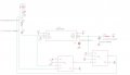
1. I am using a 555 in monostable mode to delay a signal from a photo-interrupter on an existing piece of equipment then delivering that signal through some logic gates back to the PCB on the equipment. All power and grounds come from that PCB over a wiring harness.
2. The input pulse comes from 5V being supplied from 2 photo-interrupters which then go low when the flags block the beam.
3. I have bench tested this and tested it on the equipment with a breadboard. The circuit works as intended except for after being left for ~3-4 hours with the trigger pulse at 5V. After this, the photo-interrupters give a reading of 600mV high, instead of 5V. It seems to me as if the reverse current from the trigger pin is somehow harming the transistor etc. in the photo-interrupter? Just a guess there. Unfortunately, there is no way to distinguish any markings on the interrupters to pull a datasheet on them. The current at pin 2 is around 50mA
I've attached a schema of the circuit. U1, U2 are the logic gates. That part works as intended. C1 is 180microFarad, C2 10microfarad, R2 10kOhm, R1 100Ohm.
Any ideas are why the photo-interrupters are breaking?
Thanks
I am pretty new at dealing with ICs, transistors, etc. so forgive me for any inexperience that might come out. I'll explain the operation of the circuit before I get to the question.
1. I am using a 555 in monostable mode to delay a signal from a photo-interrupter on an existing piece of equipment then delivering that signal through some logic gates back to the PCB on the equipment. All power and grounds come from that PCB over a wiring harness.
2. The input pulse comes from 5V being supplied from 2 photo-interrupters which then go low when the flags block the beam.
3. I have bench tested this and tested it on the equipment with a breadboard. The circuit works as intended except for after being left for ~3-4 hours with the trigger pulse at 5V. After this, the photo-interrupters give a reading of 600mV high, instead of 5V. It seems to me as if the reverse current from the trigger pin is somehow harming the transistor etc. in the photo-interrupter? Just a guess there. Unfortunately, there is no way to distinguish any markings on the interrupters to pull a datasheet on them. The current at pin 2 is around 50mA
I've attached a schema of the circuit. U1, U2 are the logic gates. That part works as intended. C1 is 180microFarad, C2 10microfarad, R2 10kOhm, R1 100Ohm.
Any ideas are why the photo-interrupters are breaking?
Thanks
Attachments
-
 64 KB Views: 26


