
Been a while but lately my interests have expanded to higher powered and tuning circuits. I wanted to build my own arc welder using a couple of old microwave transformers. I know it can be done and I have the materials to build and control output power but would it be feasible to include DC output as well, pulsed I'm sure. I have several 48v .38a adapters but I'm not sure what circuit would allow operation, if at all. I can go the 120vac in but I understand DC has its merits as well/safety. Any ideas or am I barking up a fallen tree?
DC/AC welder?
- Thread starter ConstructionK88
- Start date
Scroll to continue with content
MaxHeadRoom
- Joined Jul 18, 2013
- 28,684
The characteristics of a SMAW arc welder is that a high voltage is initially applied in order to strike the arc, once this occurs the voltage collapses to a much low level at suitable current.
You may find the same effect using a MW transformer if leaving the magnetic shunt in place as this produces a similar effect, there are a few Utube videos out there on building one.
Max.
You may find the same effect using a MW transformer if leaving the magnetic shunt in place as this produces a similar effect, there are a few Utube videos out there on building one.
Max.
Thank you. Building one isn't an issue at all and I intend on leaving the shunt so there will be a small constant load on the transformer to prevent heating. I just didn't know if it was possible to build, say, a pwm for DC output that would allow operation? Certainly the volage of 50v is to low but I can build a rectifier for higher DC input. It's mostly about if it'll work, can I control it, and is it even worth having DC output when I know AC is much easier. I had considered a small cap bank to provide that initial HV jolt and operation would keep it safely depleted?
Hi K88! The MOTs are not well suited for any welder making except the point-welder, where 2...4 kW is just exact match. For electrode welder the 100-150 A are must to be at 25 V thus the full 16 Amps from 240V net are mandatory. This is available ONLY by means of ferrite trafo. And not in the last place there stands UC3844/3845 and IRG4PC40W. The excellentl example is indeed http://www.danyk.cz/svar.html (note English text button in it). Probably may thing about MOT (actually two in serie) into wire-welder construction (I mean MIG), where 100A is enough and construction anyway will contain the those damn capacitor battery making MIG clumsy (just dont trust anyone telling You may have less than quarter Farad of 50V capacitors. Practically it are 6 pcs of 20 000 mkF x50V to have a quality sewing. Without it one have a oxide piles instead of nice sew.
PS. Making a pwm for trafo not be able to work anywhere above 50 Hz when industrial standard is 50 kHz is anachronism. And it takes an enormous weight where may stand the 1 kilogram it occupies the 40.
PS. Making a pwm for trafo not be able to work anywhere above 50 Hz when industrial standard is 50 kHz is anachronism. And it takes an enormous weight where may stand the 1 kilogram it occupies the 40.
Thank you friends. Ill give it a much more indepth looksee later. Might i add that i intended to use multiple transformers to provide a large current but minimal voltage. I know its possible and it will weld. Also i should have explained i only intend to weld thin metals. 1/16"-1/8", maybe a little thicker but unlikely. As in it doesnt have to be very strong. just working. Im mostly hung up on how to control output and if allowing it to operate dc is of any real use. I do love how he made his own high current output coil from copper sheeting. that gives me the idea to make my own as well.
If you're talking about the one in the link, you do know that he isn't using a microwave transformer don't you?I do love how he made his own high current output coil from copper sheeting. that gives me the idea to make my own as well.
Likely isnt. I am currently using(punny?) 2 mots and one large halide lamp transformer. I cant test the amp output but the voltage will be around 30v. Need to redo the primary on the lamp trans, its to large. So far it will turn a coat hanger into a white hot spaghetti noddle in about 3 or so seconds and puddles it just as quick, I guess enough amps for 6013 rods? It is quite noisy though.
Just Another Sparky
- Joined Dec 8, 2019
- 244
The trouble I see with using fixed-shunt transformers is that you won't have independent control of output voltage and current.
A traditional magnetic style arc welder functions through the use of an adjustable magnetic shunt to control how much magnetic flux is transmitted from the primary to the secondary. Adjusting the position of the shunt changes the output current characteristics without necessarily causing a proportional change to the open circuit voltage. In addition, nicer DC machines often include a separate inductor in series to oppose sudden changes in output current. These two factors help with both striking and sustaining an arc.
With MOTs, your shunt is fixed. The only way to control output current is by reducing input voltage. (Or modifying the shunt) Reducing the input voltage reduces the maximum open-circuit voltage available, hindering your ability to strike/sustain an arc. While this doesn't make it impossible to weld, it doesn't do you any favors either.
Thanks Sparky. I did intend on minute adjustments but wide swings arent that important. What i intend to weld really isnt subject to good or bad welds or consistent seams. Its to spot rebar to blade steels as a forging handle and to occasionally touch up on my forge blower ect. Need not be pretty but simply join metal together here and there. Is there a way to build my own variable shunt transformer? I have heaps of mild 1/4"x1 1/2" steel bars. Could i build my own transformer to suit my needs?
Just Another Sparky
- Joined Dec 8, 2019
- 244
The easiest thing that comes to mind with that idea is devising some way to slide the factory shunts in and out of the transformer core on demand. Mind you, this will only allow you to increase the output current from factory specs.
Given this is line frequency AC you will need to use insulated electrical steel lamina to build your own shunt or core. CRS/HRS barstock will be very lossy.
You could maybe try some scrapyards if you want. You might be able to find an old welder with a viable core inside of it. It's my understanding that those sorts of places only charge by the pound.
Am I to assume that other than line frequency would be better? If so is it possible to build something to change that? Also I can just go all out and hook to 220v and scatter and splatter them rods but i simply feel more comfortable with 110v. Indeed they do charge by the pound. Gold standard 
Just Another Sparky
- Joined Dec 8, 2019
- 244
Different frequencies, different material requirements. Old, ancient DC electromagnets used to be made from a single piece of steel. Line voltage equipment is usually made from laminated steel. 1~10 Kilohertz and up generally entails the use of ferroceramics.
On paper you could use some kind of series reactor to limit your current at line voltage like you suggest, but you'll need a very large branch circuit to supply 90 or more amps for welding and then you'll be paying for all the reactive power passing through your meter. And then there's the obvious danger of electric shock.
On paper you could use some kind of series reactor to limit your current at line voltage like you suggest, but you'll need a very large branch circuit to supply 90 or more amps for welding and then you'll be paying for all the reactive power passing through your meter. And then there's the obvious danger of electric shock.
Well that doesnt sound very promising, for my needs. Here shortly Im going to town to get a box of 6013 rods and test out what i have at the moment. Ill likely have to tweak as i go but confident i can make it work. Id like to test my amps out but i dont have a meter thatll handle over 10A.
Just Another Sparky
- Joined Dec 8, 2019
- 244
You could construct a crude current shunt using a length of wire with known resistance.
Chapter 9, Table 8 of the NEC provides DC resistance per thousand feet for copper and aluminum building wires.
Chapter 9, Table 8 of the NEC provides DC resistance per thousand feet for copper and aluminum building wires.
I appreciate that! I guess it's a step forward. 3016 are rated for 40ish amps and I'm certain mine packs that much. Slightly off topic and probably not easily possible but would large HV mid current diodes banked together on output give me pulsed DC or should I keep that on the input? I scrap old electronic's more than I use them so I have quite a stock pile.
Also note the trans I plan on using when I improve design can't be manipulated in any way. It's built like a T with 2 Ls. So 3 piece. My mots are 2 piece but rather small
Alrighty my friends it does work! While not deleterious to operation the darn things are very loud. I mean skull crackingly loud buzzzzzzzzzzzzzzzzzz! Is there a way to fix this or should i shove it into a box or bury it underground. Addendum: the noise was very deleterious. they burned out. Not all is lost. i have found one transformer that i can replicate that is very quite
Last edited:
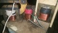
Im now using 3 of the 3piece T&L transformers. while quiet they dont seem to be delivering the amperage i need. The total output is around 28v, more than the original that worked. I am using the secondary windings as primaries, for reasons, and i reduced them to about half of what they were. I can only guess the original was about 500 wraps. I can go less but im worried they will overheat. They are nearly as thick as the primary on a MOT. Should i reduce the primary wraps to get the desired amperage/maybe more voltage for start or change my secondaries to fewer wraps? I cant quite wrap my head around whats going wrong here. The primaries are parallel and second in series. They are wrapped same direction as primary. I know a picture isn't worth a thousand words but maybe a few ideas?
Attachments
-
 4.1 MB Views: 9
About to lose all Situational Hope & Inventive Thoughts on this project


