Hi everyone,
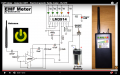
I would like to build an EM detector and I found the following circuit on this YouTube video.
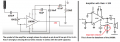
I don't feel like just doing it without understanding the way it works so I tried to figure out what the different parts of the circuit were doing. In that case I think it's just a bunch of different filters, so I tried calculating the cut-off frequencies and it didn't really add up. So I left a comment on the video but never got any reply... So I'm turning to you")
I'm a little confused by the 10nF capacitor. Wouldn't this capacitor filter almost any frequency above 160KHz? At 160KHz the capacitive reactance is at 100 Ohms. And the RC filter that follows only filters everything under 15Hz right? So what's the point? The potentiometer after the antenna is a high pass filter right? So it can filter out very low frequencies, is that it?
Every insight into the circuit is welcome (no need to explain the part with the LM3914 though). Thanks!!
I would like to build an EM detector and I found the following circuit on this YouTube video.
I don't feel like just doing it without understanding the way it works so I tried to figure out what the different parts of the circuit were doing. In that case I think it's just a bunch of different filters, so I tried calculating the cut-off frequencies and it didn't really add up. So I left a comment on the video but never got any reply... So I'm turning to you
I'm a little confused by the 10nF capacitor. Wouldn't this capacitor filter almost any frequency above 160KHz? At 160KHz the capacitive reactance is at 100 Ohms. And the RC filter that follows only filters everything under 15Hz right? So what's the point? The potentiometer after the antenna is a high pass filter right? So it can filter out very low frequencies, is that it?
Every insight into the circuit is welcome (no need to explain the part with the LM3914 though). Thanks!!
Attachments
-
 520.8 KB Views: 18