Modified AC Generator but 0 AC Voltage

Thread Starter

sourceless

Joined Oct 28, 2019
26
Hi, guys!
3dprinted and built the following generator off thingiverse: https://www.thingiverse.com/thing:1693579

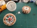
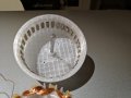
Then I wanted to modify it by building an outside rotor with the same number of magnets (32 magnets in halbach array = 16 poles). The idea was to lower the gap between coil & magnet and increase the radius a bit for higher lever force(not sure if that's the term)

You can see the new design on top. At the bottom is the original.

Unfortunately the new design doesn't do anything. Just 0 Voltage no matter how much rpm I put in. The coil has 4ohm resistance, it's serpentine coil. I though that I've shorted it somewhere (even shorted should get some minimal voltage?). So decided to put a second coil - same thing.
The halbach array is working as it should as the field is on the inside (testing with metal rod). Field is alternating when turned (testing with a compass).

Does anyone has any clue what's the problem? Could the change of radius make the currents in the coil cancel out completely(I can't be that good :))?
 

Marley

Joined Apr 4, 2016
502
I have to say it doesn't look like a very efficient design to me. Surprised the coils are not wound on some sort of laminated iron stator. The magnetic air path needs to be as short as possible.

Still, ought to generate something. If you have a changing magnetic field cutting a wire, emf will be created.

Are you sure you have wound it correctly? If at one coil positive emf is exactly balanced with negative emf in another coil the result will be zero.
 

Thread Starter

sourceless

Joined Oct 28, 2019
26
Hi,
yes, it's bad design, because of the plastic stator. I'm doing it just for fun. This is my first iteration so I wanted a bit wider gap.

Got the coil design from here: https://www.thingiverse.com/thing:1766551

But now when I look at it, the horizontal bars on the stators on mine are a lot more thinner. I wanted more place for the wire but this makes the coil different width. And when you take in mind that the "thing:1766551" design uses different width magnets it seems I've messed everything up, right? Ups, some real engineering here :)

How can I know how many degrees should the coil occupy?
 

Attachments

Last edited:

Thread Starter

sourceless

Joined Oct 28, 2019
26
Later I plan to 3dprint the stator with ProtoPasta - plastic with metal dust inside to emulate the armature. Maybe do the same for the rotor, but from what I've read it's not vital as it's a halbach array. Magnetic force is very little on the outside and strong on the inside so it must be ok for hobby.
 

shortbus

Joined Sep 30, 2009
10,045
as it's a halbach array
Really hard to tell from your pictures but don't think you have a Halbach array with the way you magnets a situated. Where did you see that your magnet arrangement is a Halbach array? I doesn't look like the one shown here - https://en.wikipedia.org/wiki/Halbach_array Or here - https://www.kjmagnetics.com/blog.asp?p=halbach-arrays Unless you have a couple of different styles of magnets that look alike but have different pole orientations.

Also did you see in the link you posted that the author said he didn't have it working?
 

Thread Starter

sourceless

Joined Oct 28, 2019
26
Hey, shortbus!
I'm no expert by any means, but pretty confident that it's a halbach. I built this one: thing:1693579
It gives 3V AC and lights a diode by hand cranking. Used exactly this pic you posted to build it: https://www.kjmagnetics.com/images/blog/normalvshalbach.png

This one: thing:1766551 I haven't built but was inspired by the previous - just bigger. Poster says it gives 5V.

Read all comments, didn't see one saying it's not working.

I just wanted to light a diode and be happy with it. Now I'd like to debug it.

Could it be that because the radius is bigger -> magnets are further apart and lower the intensity of the field. But still on the outside magnets are quite weak, on the inside strong.

p.s. - Atlas Shrugged was a nice one!
 

shortbus

Joined Sep 30, 2009
10,045
I'm no expert by any means, but pretty confident that it's a halbach. I built this one: thing:1693579
I'm no expert either, but if you compare this picture from that link -
1572880545751.png

to your rotor picture and magnets you should if you're honest see the difference in the magnets and how they are different from what your doing. Image in post#5. If you can't see the difference in the two, no literature will help.
 

Thread Starter

sourceless

Joined Oct 28, 2019
26
That's exactly the model I built - and it's working. Same magnets.
But the picture you are posting does not have the magnets in a halbach array.

Assembled array is this one:
 

shortbus

Joined Sep 30, 2009
10,045
But the picture you are posting does not have the magnets in a halbach array.
Sure it does, if they are done like the red lines on the picture in post #11. But the ones in you picture in post #5 are nothing like that, the ones in Post #5 are NOT a Halbach in any form I know of. You really don't see any difference in the two pictures?
 

Thread Starter

sourceless

Joined Oct 28, 2019
26
Yep, did same arrangement as pic in post #11 for the 2 of the generators. Only difference is with one the field is on the outside (original), mine has it on the inside. Maybe you can't see it clearly because some of the marker was wiped out.

Also when I get the rotor near to the compass and when I turn it slowly it shows 8N + 8S poles. So it must be ok.

1. Could it be because of bigger distance my rotor has between magnets, which might make the magnetic field weaker.
2. Could it be because the strong field is on the inside it gets squashed in a way that needs change of the degree each coil occupies.

Today I placed a single normal(round not serpentine) coil with about 25 turns and I get about -4 to 4 mV when turned very slowly(measured with the DC V because AC V doesn't have miliVolts).
 
Last edited:

shortbus

Joined Sep 30, 2009
10,045
You need to do some googling on how things work. Can you give a link to the EXACT magnets your using in the rotor in post 5? I still say it isn't a Halbach.
 

Thread Starter

sourceless

Joined Oct 28, 2019
26
I googled about magnet/coil ratio, checked out some designs. The design I'm making is a complete copy of thing:1693579 that has the magnets on the inside, so it has:
- 16 pole (32 magnets total, 16 magnets in between are just to channel the magnetic flux) - same magnet count but on the outside of the coil with larger space between them(most probably kills the whole halbach effect)
- 3 * 8 coils = 24 coils (3 serpentine coils with 8 tops("coils") in this case) - same number of coils per phase but I'm adding a third because the original has only two phases(2 serpentine coils with 8 tops) - this changes the radius that each "coil" occupies
which is 24 / 16 = 1.5 coil/magnet ratio

This design is similar: https://www.instructables.com/id/600-Watt-3d-printed-Halbach-Array-Brushless-DC-Ele
but has 34 magnets & 3 * 9 = 27 coils with thicker gauge wire

I'm using 0.5mm thick wire.

Here I've placed all pics together to have them at the same time. I've tried to match the green Halbach array example picture on the left as much as possible to the magnets at it's left.
- I check 1 magnet with the compass and mark it's North
- line magnets behind it on a line and mark them too
- then I arrange the magnets as the example of a Halbach array
Have I done something wrong?IMG_20191028_192943.jpg
 
Last edited:

shortbus

Joined Sep 30, 2009
10,045
I ask again for a link to the magnets you're using.

See the difference in the magnets in the green drawing and the ones your using??? I have never seen a flat, thin magnet like you're using have the same pole type as the square ones shown in the green drawing.

Having the magnets arranged like it looks like you do, N-N-S-N-N does not make a Halbach. Do you see how the poles are arranged in the gray picture? That isn't how your magnets are arranged. Unless you found so different type of magnet, which to prove it would be as easy as showing a link to them.

Also see how the magnets are close together in both Halbach drawings? Are the ones in your rotor like that?
 

cmartinez

Joined Jan 17, 2007
8,253
Methinks that if you're to use rectangular prism (instead of cubed) magnets, then you'd need two different types of magnet to build a halbach array.

Such as these:

1572998504715.png

Are these the types of magnet that you're using?
 

cmartinez

Joined Jan 17, 2007
8,253
Almost correct see my post #18. Or he could use the cubes that the guy in his link did.
I beg to differ, Shortbus... the way the magnets's poles in my previous example are arranged to match the following image shown at Wikipedia:

Linear_Halbach_Array_(Weak_side_up).png
Visualize my magnet shown on my previous post on the right as the first element of the array in the drawing, and the one on the left as the second one, and so on...
 
Top