
Hello Everyone,
I looking for a schematic for delay on power circuit for 24VDC. I would like solve this problem with componets SMD because i nned instal samll PCB in some device. Could you help me to solve this probelm. I found some schematic but on 12VDC. This PCB must delay power on in relay but author used a THT parts. Could you help me solve this issue.

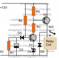
List parts:
R1 = 1o0K (Resistor to discharge C2, when power OFF)
R2 = 330K (Resistor delay)
R3= 10K
R4 = 10KR4 10K
D1 = 3V zener diode (* option)
D2 = 1N4007
D3 = 1N4148
T1 = BC547
T2 = BC557
C2 = 33uF/25V (Capacitator delay)
I looking for a schematic for delay on power circuit for 24VDC. I would like solve this problem with componets SMD because i nned instal samll PCB in some device. Could you help me to solve this probelm. I found some schematic but on 12VDC. This PCB must delay power on in relay but author used a THT parts. Could you help me solve this issue.
List parts:
R1 = 1o0K (Resistor to discharge C2, when power OFF)
R2 = 330K (Resistor delay)
R3= 10K
R4 = 10KR4 10K
D1 = 3V zener diode (* option)
D2 = 1N4007
D3 = 1N4148
T1 = BC547
T2 = BC557
C2 = 33uF/25V (Capacitator delay)
Attachments
-
 36.9 KB Views: 7


