Help identifying wifi component on a PCB

Thread Starter

feedbcak

Joined Apr 25, 2019
10
sorry for the inconvenience but i have close to zero knowledge in electronics.
TL;DR: does it have wifi capabilities?
longer story:
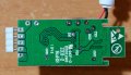
I bought a wifi RGB LED strip controller and when I connected it to 2 different LED strips, nothing happened. (Voltage and Amps are as required)
I opened the case and did some search and didn't find any indication this board has wifi in it.
(I guess im looking for a WIFI chip like this here marked in blue line:1111.jpg)

so I came here to ask if it actually has wifi capabilities in it.
if it do have wifi, then why do the LEDs not light up?
I can get soldering iron and a multimeter if needed. I have some experience with soldering so I doubt it'll be a problem.

an exact copy of my board from google (clearer image):
chip is ESP8285
board is ZJ-WFMN-A v1.1
DSC_5851.JPG

Thanks and again sorry for the inconvenience.
 

kubeek

Joined Sep 20, 2005
5,795
The ESP8285 chip has wifi, the antenna seems the same size as your reference design, my verdict is yes, this board has wifi capability. If and how it is used is a different question.
 

Thread Starter

feedbcak

Joined Apr 25, 2019
10
The ESP8285 chip has wifi, the antenna seems the same size as your reference design, my verdict is yes, this board has wifi capability. If and how it is used is a different question.
Thanks for the quick answer.
as for the LED strip (and wifi) not working, I guess I'll have to get a multimeter and check if the correct voltage is coming out of the output v+ pin?
in reference to what do I check that voltage? the red v+ cable?
 

Thread Starter

feedbcak

Joined Apr 25, 2019
10
You may want to re-flow the 3 SOT-23 components, red wire and black wire.
That 6 leg IC looks probably like the voltage regulator for the mcu but you can just check at the MCU to see if its getting power.

here is the datasheet for mcu:
https://www.espressif.com/sites/default/files/0a-esp8285_datasheet_en_v1.0_20160422.pdf
i tried to re-flow the parts you said and i dont know if i checked correctly with the multimeter, (1 probe at gnd and the other on pin #1 (VDDA)), but it supposed to show 3-3.6v going into the mcu and it shows 0, so i guess either the gets no power, or not enough.
i dont know the "path" from the v+ to the mcu's input power and couldn't find any schematics. what should be the next step?

note: i dont actually mind if the item gets ruined, but i do want to try and save it and learn some things doing it, so any experiment is welcomed :)
 

narkeleptk

Joined Mar 11, 2019
558
the 6 leg ic is probably the voltage regulator. Probe it to see if you have voltage going in and right voltage going out.

edit: removed bad datasheet
 
Last edited:

DbLoud120

Joined May 26, 2014
91

Do you have instructions with your device on how to connect it to your network?

Have you checked your router to see if this device is recognized by your network?

If you have a secure network there are certain steps required to make your device accessible.
 

Thread Starter

feedbcak

Joined Apr 25, 2019
10
the 6 leg ic is probably the voltage regulator. Probe it to see if you have voltage going in and right voltage going out.

edit: I think this is datasheet
https://www.mouser.com/datasheet/2/792/rp170x-e-844467.pdf
i really get lost with all the readings but i think this datasheet isn't the same as the ic. anyways depending on the pins i put the probes on, i get ~4.8v, ~9v, or ~12v (or their respective negative values when the probes are switched between the pins.)
from what i understand the mcu requires 3-3.6v. is there another resistor somewhere along the way that regulate the voltage to that value?

Do you have instructions with your device on how to connect it to your network?

Have you checked your router to see if this device is recognized by your network?

If you have a secure network there are certain steps required to make your device accessible.
there are no instructions, but checking online i found out i just got to connect the wifi-controller to the led strip (and power supply) and the leds should blink signifying its working. then im supposed to go to MagicHome app and a wifi ID of that led strip is supposed to show up. (and then im supposed to direct the led strips wifi to my home wifi). problem is the leds do not blink and no ID is shown in the MagicHome app.
 

Thread Starter

feedbcak

Joined Apr 25, 2019
10
It looks like GBB to me, and that is this chip apparently. Check

That is a linear reg, and the layout looks like there is and inductor and capacitor connected to it, so a step down in my mind.
what does it means? as i stated at the OP, i've little to no knowledge in electronics...
if the regulator works, then why doesnt the mcu receive power?
 

djsfantasi

Joined Apr 11, 2010
9,163
what does it means? as i stated at the OP, i've little to no knowledge in electronics...
if the regulator works, then why doesnt the mcu receive power?
There are three possibilities
  1. There is no input power (voltage) to the regulator
  2. The regulator doesn’t work
  3. The MCU doesn’t work
Devise a test for each scenario.

You’ve already stated that there is 12VDC input to the regulator. Did you test this with a meter or is that what the power supply is SUPPOSED to output.

Did you check the regulator output? Can you cut the output trace and test its output without a load?

Not sure how you can test the MCU. But if the previous two tests are good, I’d take a good look at the MCU. Or any other parts of the circuit powered by the regulator.
 

kubeek

Joined Sep 20, 2005
5,795
what does it means? as i stated at the OP, i've little to no knowledge in electronics...
if the regulator works, then why doesnt the mcu receive power?
Sorry that first part is from an older post that i thought was deleted. The rest is about that part not matching what is on the PCB.
 

Thread Starter

feedbcak

Joined Apr 25, 2019
10
There are three possibilities
  1. There is no input power (voltage) to the regulator
  2. The regulator doesn’t work
  3. The MCU doesn’t work
Devise a test for each scenario.

You’ve already stated that there is 12VDC input to the regulator. Did you test this with a meter or is that what the power supply is SUPPOSED to output.

Did you check the regulator output? Can you cut the output trace and test its output without a load?

Not sure how you can test the MCU. But if the previous two tests are good, I’d take a good look at the MCU. Or any other parts of the circuit powered by the regulator.
to be honest i don't know anymore.
i need to know how to check it correctly with the multimeter.
the datasheet has 3 types of regulator but they have 5 legs (one of them has no connection so its basically 4 legs) and my pcb's regulator has 6 legs and i can't tell what the readings of the multimeter means.
i tried putting the voltage probe on the vdd pin and the COM probe on the vout pin for each config. these are the results:
SC88A: -9.1v
SOT-23-5: 4.8v
SOT-89-5: -4.8v

doing the same with the COM probe on the ground pin gives:
SC88A: 0v
SOT-23-5: 4.8v
SOT-89-5: 0v.

in the tests above, i ignored the top middle pin in my regulator, and tested as if the top left most pin was the 5th (like in the datasheets)
hope it clarifies a bit for you guys because im stumped
 

narkeleptk

Joined Mar 11, 2019
558
Ignore that gbb datasheet it was not correct part. Use the datasheet for the MCU and check its Voltage in. If no voltage there, unhook power and use your probes set on continuity to work your way back down the line of components to see where it should be coming from. After you know the path, hook power back up and test the trail to see where voltage is lost.
Re-Read @djsfantasi post over and google some videos on how to do what he's telling you to check if your getting lost.
 

Thread Starter

feedbcak

Joined Apr 25, 2019
10
Ignore that gbb datasheet it was not correct part. Use the datasheet for the MCU and check its Voltage in. If no voltage there, unhook power and use your probes set on continuity to work your way back down the line of components to see where it should be coming from. After you know the path, hook power back up and test the trail to see where voltage is lost.
Re-Read @djsfantasi post over and google some videos on how to do what he's telling you to check if your getting lost.
just to be 100% sure, when i check if there's voltage in the mcu, i use the probes on the vdd (#1pin) and the ground (black wire)? in relation to what do i check the Vin?
 

narkeleptk

Joined Mar 11, 2019
558
actually looking at the back of the board the v33 is probably the supply for the mcu. hold your probe there and your com on gnd. its also in the side where the 3 large through holes are.
 

djsfantasi

Joined Apr 11, 2010
9,163
You test voltage between two points. In your case, between ground and the voltage being used. Without checking the datasheet, I’d say that Vdd is the positive supply for the MCU. If you have the probes as described (and my assumption is correct), the measured voltage between the two pins would be the MCU supply
 

Thread Starter

feedbcak

Joined Apr 25, 2019
10
actually looking at the back of the board the v33 is probably the supply for the mcu. hold your probe there and your com on gnd. its also in the side where the 3 large through holes are.
there's basically no voltage there.
also for the continuity, there are at least 10 different components that beep when 1 probe is set on the Vin pin of the mcu. so either everything is connected to everything in a giant mess or somethings broken somewhere

You test voltage between two points. In your case, between ground and the voltage being used. Without checking the datasheet, I’d say that Vdd is the positive supply for the MCU. If you have the probes as described (and my assumption is correct), the measured voltage between the two pins would be the MCU supply
if that's the case then it shows 0-0.10v
 
Top