Solenoid Transistor

Thread Starter

adam450

Joined Mar 19, 2019
34
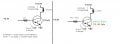
Swear I had this working the other day. I made a change and now it stopped working. The TIP transistors are rated at like 80 watts, but since the coil drops voltage, the input voltage to the transistor should be 2V or so. I have 3.3mA going into the gate of the transistor. I've seen some schematics with a gate to ground resistor. Not sure if that is needed but I know I had one while it was working. I tried R1 = 1,000ohm and R2 = 10000ohm but looking back maybe I need R1 and R2 as a voltage divider so that the voltage input to the gate is dropped?

Anyway, I've burned up like 10 transistors (TIP120 and TIP102). I was trying variable tests from 41.6 to 46 volts yesterday to test how much I could drive the transistor. It seemed everything was working yesterday. I believe I increased the R1 resistor and that was what blew up my transistor.

Going back on what i said before, if the coil has voltage drop, the drain would be +2V or so for the transistor. The gate even with the resistor could in theory be higher voltage than drain depending on resistance in the transistor. Maybe this is why my transistors are blowing up? This is for a pinball machine and everyone says those transistors are valid to use. I might have to try some R1/R2 pairs and see if it works out better.

upload_2019-3-19_2-42-35.png
 

danadak

Joined Mar 10, 2018
4,057
upload_2019-3-19_9-42-10.png

Your max Ic (DC) for a TIP120 IS 5A.

The Vcesat at 4A is ~ 3V

So when relay on Pdiss = 3V x 4A = 12 W. Has to be on a heatsink.

Also look at required Ibase for Vcesat, its around 16 mA for Ic = 4A.

So to determine Rbase = (3.3 - Vbesat) / 16 mA, Vbesat ~ 2.25V. Note I interpolated
this from the above spec, not graph.

So Rbase = (3.3 - 2.25) / 16mA =~ 65 ohms.

Note, your Irelay of 2.7 A tells us that TIP120 was way out of saturation. Eg. its
base drive way too low. In fact TIP120 was then dissipating ~

Vce = (46 - 2.7A x 11.5 ohms) = ~ 15V

So Pdiss = 2.7A x 15V =~ 42W, enough to cook a steer on a grill if not properly
heatsunk. The rise of Tjunction inside TIP120, given its ~ 2 C/W thermal R,
junction to case, was then ~ 85 degrees C over case temp, if case was at 25 C
then Tj =~ 110C. Past boiling water, super heated steam.....:)

Lastly what is sourcing the current from the 3.3V you show for base drive ?
If it is a micro thats another problem, most I/O pins on a UP cannot source
enough current to meet 16 mA. You can possibly parallel a couple of outputs,
look at UP spec. And looking at its specs when output is loaded it no longer
is at 3.3V, so you have to account for that in your TIP120 base R calculation.


Regards, Dana.
 
Last edited:

Thread Starter

adam450

Joined Mar 19, 2019
34
Ok, I'll do some extra testing, yes I believe originally I may have had a 220ohm resistor to the base input. I was trying to increase this to 1,000 or more to see if I could limit the current draw through the coil. It's for a pinball machine and my PSU is 7.3 Amps, so I was trying to figure out a way to lower the coil Amp draw. Running 2 coils to flip the ball around was already going to take almost 7Amps.

Not sure what you mean about the MCU sourcing. 3.3V output pin w/ 220ohm resistor = 16mA. In the original schematic I posted it should be drawing 3.3V/1000 = 3.3mA. Shouldn't be oversourcing from the MCU.

Supposing that I can get this working, I guess the only way in this scenario to reduce my coil amp draw would be to increase it's resistance. Or get a power supply with more power.
 

ericgibbs

Joined Jan 29, 2010
18,849
Not sure what you mean about the MCU sourcing. 3.3V output pin w/ 220ohm resistor = 16mA. In the original schematic I posted it should be drawing 3.3V/1000 = 3.3mA. Shouldn't be oversourcing from the MCU.
hi adam,
Its is not 3.3v/1000R, you must subtract two forward Vbe transistor drops from the 3.3V, so thats (3.3v-1.4v) /1000R = ~1.9mA

If you 'starve the TIP of Base current it will not saturate and it will rapidly over heat.
E

EDIT:
Measuring the Vbe on the simulation its higher than 1.4V it is 1.7V.
so 3.3v -1.7v =1.6V/1000R =~ 1.6mA as the sim shows.
 

danadak

Joined Mar 10, 2018
4,057
You cant control the current in a repeatable manner by starving the
base current.. T effects on gain and junction voltage will totally undo
your goal. In fact as it heats up the Ib and Ic will rise, and its regener-
ative until something stops the Ib increasing or it melts.

3.3 from MCU., yes 3.3 mA would have been achievable, but it would not have been at
3.3V when you loaded the output. And as we have all pointed out you are not saturating
the transistor, so they are burning up. What do they have for a heat sink ? A picture
would be helpful.

Note the sat curves in the datasheet show a forced beta of 250, which says for erics
sim model (which I think the device model the simulator supplied sucks) Ib = 3.5A / 250
= 14 mA. That is much closer to part of datasheet I posted earlier where it shows 12 mA
for 3A and 20 mA for 5A .

Forced beta is the term used in industry of what conditions in base, current needed,
will force the transistor into saturation. beta = Ic / Ib.

Another approach, if you decide not to pump 16 mA into the base, is use a MOSFET
with low Rdson, to get a better switch ohms. But would have to be a logic level
MOSFET and there could be other design issues involved. Like limiting the current
from the 3.3 source because its charging very large gate C of MOSFET.

To solve relay max current problem you could add some R in series with Relay to lower
its current draw, but R would have to have right power dissipation. And you need to
evaluate relays min holding current needed.


Regards, Dana.
 
Last edited:

bertus

Joined Apr 5, 2008
22,277
Hello,

He has used the wrong schematic symbol.
The used symbol is for a J-fet and he states to use the TIP120 and TIP102.
Both are NPN Darlington transistors.

Bertus
 

Thread Starter

adam450

Joined Mar 19, 2019
34
Heatsink
https://www.jameco.com/z/531102B02500-TO-220-Heat-Sink-1-Hole_326713.html

"If you 'starve the TIP of Base current it will not saturate and it will rapidly over heat."
"You cant control the current in a repeatable manner by starving the
base current."

That's basically what I came to realize. I was hoping to limit my coil current to not steal so much power from my power supply. I see that reading more and learning some numbers, that the 220ohm resistor I think I originally had was working just fine and would draw a correct base current.

Where did the Vbe number come from? This diagram? Once I know that, I think I got the mathematics correct to figure out the proper numbers. Ideally this will run at 48V. Thanks people.

upload_2019-3-19_14-29-2.png
 

Thread Starter

adam450

Joined Mar 19, 2019
34
*I forgot, I do have a diode across my solenoid to prevent any feedback.

I attached my working an non-working circuits. I tried the same layout, 220ohm resistor to base for a TIP120+TIP102.
-TIP120 works fine. It does burn out if I have a hold time of 2 seconds but that's not what I'm intending for the final design.
-My TIP102's burn out instantly. They aren't even hot to the touch and I left them on for several seconds. Maybe once it breaks down it doesn't produce much power dissipation.

I went back, re-ran the numbers and at 3.3Amps, the base resistor + current appear to be calculated properly from my drawing. Any thoughts? Why would a TIP102 die when everyone online says it is a direct replacement and beefier than a TIP120. Why did it die with the 120ohm resistor as well? Also my TIP120 was able to run without the heatsink if I limit the on time to less than 1 second. I was able to turn it on and off repeatedly and not burn out.

I appreciate the help, my realm is in videogame software, not hardware.
 

Attachments

Last edited:

Thread Starter

adam450

Joined Mar 19, 2019
34
Vbe in the drawing is 1.7V, not Vce. Per the graph on the datasheet. I've tried at this point 1200ohm, 1000ohm, 220ohm, 33ohm base on the TIP102 and nothing will work on it.
 
Last edited:

ericgibbs

Joined Jan 29, 2010
18,849
hi,
Your calculations shown in your first diagram are incorrect.
Look at the image I posted in post#2, the Collector/load current is 3.5A not 2.7Amps, which makes the dissipation in the load ~ 140Watts not 112Watts.

The TIP120 is operating outside its Safe Operating Area, use a power N MOSFET with a heat sink.
E
 

Attachments

danadak

Joined Mar 10, 2018
4,057
Assuming your 3.3V supply is “stiff”, its 3.3, then
Ib = (3.3 – 1.7) / 220 =~7.3 mA. But the 1.7 comes from
curve that says forced beta is 250, that in turn implies
Ib should be = 3.3 / 250 = 13.2 mA. You are under driving
base, or the 3.3V source for base circuit is collapsing under
load.

If we assume 3.3 is not collapsing, then at Ib = 7.3 mA
from collector sat curves (remember all these curves
typical at Tj = 25C), Vce = ~ 1.35 V, so Pdiss = 3.3A x
1.35 V =~ 4.45W which is well within SOA if transistor
switching properly speedwise.

The TIP102 datasheet also shows a lower thermal R j-c
than TIP120. ~ 25% lower.

So I still think you are under driving the base of the TIP.
or that the 3.3V source for the base drive is dropping
V when loaded. Eg, you are not getting the base drive you
think you are. Which would explain why your 33 ohm
test did not work.

Leaving TIP out of circuit load the 3.3V with 100 ohms,
what is V across R ?

One other consideration, if TIP not switching fast, slow ramp
on base drive, then that would result in high Pdiss due to
transistor not being in saturation, eg. having high Vce and Ic
simultaneously. A single shot trigger on a scope looking at
collector will tell you whats going on there.


Regards, Dana.
 
Last edited:

Thread Starter

adam450

Joined Mar 19, 2019
34
@ericgibbs
I see that the graph you drew put the Collector voltage at 48V, am I not supposed to account for the load dropping voltage? The transistor isn't getting 48V at its Drain.

I meant to put 100ohm I believe in my second drawing. I see why it blows up it is a different package on the TIP102. Ideally I was going to use an IRF3205 N-Mosfet but I blew a couple of those up and moved back to my transistor which seemed to be working.
 

bertus

Joined Apr 5, 2008
22,277
Hello,

Most likely the reason why the IRF3205 blows is that it was not fully activated:

IRF3205_specs.png

With 3,3 Volts on the gate, it is still in the linear range.
If you want to use a mosfet, look for some logic gate mosfets.

Bertus
 

ericgibbs

Joined Jan 29, 2010
18,849
hi adam.
The TIP120 does not have a Drain pin, it is the Collector, a Drain pin refers to a FET.

When there is no Base drive input the Collector will be at 41.5V.
If you restrict the Base current when you try to turn the TIP120 On, if there is insufficient Base current to saturate, the TIP120 it will get hot.
This why we keep saying you must ensure that the Base current, from the 3.3V control source is sufficient to saturate the transistor.

Using a 100R Base resistor from 3,3v will give a Base current of 3,3v-1.7v = 1.6v/100R = 16mA.

So to saturate the transistor with a 3.5Amp collector current the current gain must be at least 3.5A/0.016A =200

Check the TIP120 datasheet to confirm this.
E
 

Attachments

Thread Starter

adam450

Joined Mar 19, 2019
34
3.3Amps CE, 3.3A / 250beta = .0132 (Base Current needed to saturate 3.3Amps across the transistor)
3.3V-1.7V = 1.6V drop needed at base, 1.6V/.0132A = 121ohm base to get 13.2mA

^I didnt have a 121 ohm resistor so I used a 100ohm. Which means I provided 1.6/100ohm = 16mA to base.

So as you guys have kept saying not enough current into base, the ideal is 13.2 mA. How close do I have to get to that IC/IB = 250, I assumed providing more (16mA) would be fine because it is just the point of oversaturation and not doing much. Which did work on my transistor.

I'll have to take a look at my IRF3205's and also look at some other logic level mosfets. Thanks.
 
Last edited:
Top