Micro controlled shift box project

Thread Starter

Blinkyblinx9

Joined Dec 6, 2018
16
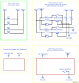
I was not sure where to post this as it uses non automotive electronics in an automotive application so if its in the wrong place please tell me and I will remove this and post it in the appropriate place. I have been working on a plan for a shift box for my track car with an auto trans for a few days now. I want to use up/down inputs to tell a micro-controller what solenoids to switch on and off within the transmission instead of switching the solenoids on and off myself. I would also like to use the tachometer signal to prevent the micro-controller from downshifting into a gear when I'm at too high of an RPM thus preventing engine damage if my paddles or shift lever is bumped in error. I also need to display what gear I'm but I will be leaving that for another time as I will be doing extensive testing before I actually try using this on the track. The switches are straight forward but feel free to correct me on that section if it is off. The solenoid control and engine speed signal are of concern to me. I think I got the solenoid control correct, forgive not having values or specific parts listed it was kind of rushed. If there is anything wrong please let me know how I can design it any better. IDK if the tach signal is at 5v or 12v but it is pulse frequency not pulse width so that's blank for now however I was planning on using an opto isolator to step the pulses down to a voltage more manageable by the controller. The pressure solenoid control will be PWM converted to a 12v higher current circuit but I have little experience working with PWM. I have no idea how to do any of that so that's the second reason I am here. I know this was long winded so I want to thank anyone who even read this in advance.
 

Attachments

Sensacell

Joined Jun 19, 2012
3,449
I would work on defining the detailed IO requirements first
List all the actuators and sensors, define voltage and current input and output requirements.
Create a timing diagram and operational flowchart.

You will need to build a simulator / mock-up so you don't destroy your transmission while you write the code.
As anyone experienced in writing code for electro-mechanical systems can attest, It will go totally haywire, over-and-over as you debug the code, causing carnage if you use the real mechanics.
 

Thread Starter

Blinkyblinx9

Joined Dec 6, 2018
16
I I'm not sure what you mean by I/O requirements. Forgive me I have fixed a few boards but have never designed something of my own. This is really quite simple though. You click a button for up or down, the MC receives a 5v signal at one of 2 terminals, it then turns the solenoids on and off accordingly to achieve the desired gear assuming the engine rpm isn't too high. I forgot to mention it's a 90s car so it's literally as simple as 4 automotive components. The engine speed signal (which will be pulled directly from the tachometer wire terminal), the 2 shift solenoids and 1 pressure solenoid (which are directly in the transmission with no secret sauce). They are as simple as power in then they ground to the transmission. The transmission pressure unregulated is about 300psi with the solenoid off. Its usually regulated to 150psi or so. Shifting at 300 wont break anything it just makes it VERY uncomfortable when downshifting. Like neck snapingly uncomfortable lol. Really I just want that run at about 65-75% duty. I will be extensively testing it with 12v lights to simulate solenoid actuation while I program everything to make sure it functions properly. The programming is something else entirely. I actually have experience writing code so it shouldnt be that big if a deal for me. Going back to automatic shifting is as simple as turning the MC off and turning the TCU back on. I guess I'm not really worried about the car. The solenoids work off the cars 12v system and I already have a simple shift box in place it's just too basic and requires correct button presses manually activating the solenoids to change gears. I have messed that up few times but have been lucky thus far. It's off season so I wanted to remedy this issue I'm having now while I still have 4 months to iron out the bugs once its together.
 

Thread Starter

Blinkyblinx9

Joined Dec 6, 2018
16
Ohh I think I know what you mean. As far as the automotive circuit is concerned the only thing I have to worry about is current flowing through the components controlled by the MC. The solenoids are designed to handle 12v directly from the battery so that's no issue. The shift solenoids are both .4-.7a draw depending on how voltage fluctuates (automotive circuits of this time operate anywhere between 12 and 14.5v) and the control is about 4-6a again depending on voltage. As for the MC itself and how many defined inputs I'll need I'm not really sure. I dont know what goes into the 5v to 12v high current pwm conversion. I have converted 5v to 12v before but only to operate a .2a fan. Not exactly a high draw component. Lol Thanks again for your help. I'm pretty lost as to the PWM and pulse frequency conversions. Idk if most MCs like an arduino can even interpret drastic changes pulse frequency.
 

Reloadron

Joined Jan 15, 2015
7,517
OK, just to get things on the same channel starting with the uC (Micro-Controller) the I/O is simple the In / Out so for example if you push an up shift button something happens so that In triggers an Out and if you push a Down Shift button it triggers an Out but only IF another condition is met like Speed is Less Than a set pre determined speed.

The uC outputs DO (Digital Out) would likely drive a solenoid as the uC alone will not source enough current out, so we add a MOSFET or similar to handle switching the solenoid current. That is all hardware which comes later. There are dozens of micro controllers which will do what you are looking to do.

The way I suggest you start is to get a pencil with an eraser and a blank sheet of white paper and outline everything you want to happen based on any events like Up Shift or Down Shift (upShift dnShift) and the conditions. You also need to decide for example on dnShift do you want tach speed or vehicle speed. Things like that.

Ron
 

Thread Starter

Blinkyblinx9

Joined Dec 6, 2018
16
I have most of that figured out already lol. I attached a VERY partial schematic I have worked on for a day or so between. Idk if that uploaded or not. My biggest problem is the circuitry and my main concern is not causing harm to the uC. I know it's very simple but I am not 100% how to go about it.
shortbus: The RPM signal is actually two pulses per rotation as per my ostrich setup.
Reloadron: output of any shift is based on the input requested, it's current output, and in the case of a downshift the engine rpm being low enough say 12khz based on 2 pulses per rotation. Yes, I want to use engine RPM signal but only to prevent an accidental downshift at higher rpm. Again I know how to write the logic for this I just dont know how to design the circuit to convert uC 5v output to operate the 12v automotive system.
 

Reloadron

Joined Jan 15, 2015
7,517
I just dont know how to design the circuit to convert uC 5v output to operate the 12v automotive system.
Relatively easy, while I don't have a schematic ready using solenoids I can give you one using LEDs as the load.

5050 LED String.png

The DIO 1, 2 and 3 are Digital Outputs from a uC. The Red, Green and Blue are the signals, in your case to control your solenoids. A simple diode would be added across each solenoid coil, commonly called a "flyback" or "snubber" diode. The MOSFETS are common what is called a "logic level MOSFET" which is a nice way of saying the approximately 5.0 Volt output of a uC is adequate to turn them on so they act like a switch turning the solenoids Off or On.

The uC is your choice but I suggest something simple and easy to interface like the Arduino family as it is already on a board, easy to write programming code to and relatively inexpensive.

Ron
 

Thread Starter

Blinkyblinx9

Joined Dec 6, 2018
16
Okay, I wasn't aware I didn't have to use a relay. I assumed since I was using a 5v circuit to manipulate a relatively unstable 12v circuit I needed something to isolate the uC from the higher voltages. Does that then ground from the transistors/mosfets to the 12v automotive ground? I understand my required resistors and other components will be different based on current and voltage tolerances.

Thank you for the suggestion as to what uC to use. I have already decided on an arduino as I have written some very basic code for it years ago and am semi familiar with it.
 

Reloadron

Joined Jan 15, 2015
7,517
Okay, I wasn't aware I didn't have to use a relay. I assumed since I was using a 5v circuit to manipulate a relatively unstable 12v circuit I needed something to isolate the uC from the higher voltages. Does that then ground from the transistors/mosfets to the 12v automotive ground? I understand my required resistors and other components will be different based on current and voltage tolerances.

Thank you for the suggestion as to what uC to use. I have already decided on an arduino as I have written some very basic code for it years ago and am semi familiar with it.
Yeah, in my example the solenoid ground is made through the MOSFETs. It is called "low side switching" but for that to work the solenoids need two leads for the coil meaning that the solenoid common can't be where it bolts to chassis ground. That's all you need and actually any MOSFET will work as long as it can handle the current load of the solenoids.

Ron
 

Thread Starter

Blinkyblinx9

Joined Dec 6, 2018
16
Ahhhhhh, unfortunately in this case the solenoids are on the valve body inside the transmission and their ground wire connects directly to the inside of the transmission. I only have the hot wires to work with unfortunately which is why I had the relay in place. I'm so sorry, I did not explain the circumstances that led me to write up that part of the design as I did. Again idk if the image attached or not. I apologise again for my ignorance. I am just so new to designing something like this.
 
Last edited:

Reloadron

Joined Jan 15, 2015
7,517
Ahhhhhh, unfortunately in this case the solenoids are on the valve body inside the transmission and their ground wire connects directly to the inside of the transmission. I only have the hot wires to work with unfortunately which is why I had the relay in place. I'm so sorry, I did not explain the circumstances that led me to write up that part of the design as I did. Again idk if the image attached or not. I apologise again for my ignorance. I am just so new to designing something like this.
OK, no problem, just means we use high side switching. Rather than an N Channel MOSFET like I used we use a P Channel MOSFET and switch the high side of the solenoid coils. A Google of for example "arduino fqp27p06" should yield some examples. Also if you look at post #24 in this Arduino thread you will see an example. We just add a simple NPN driver transistor to drive our P channel MOSFET for high side switching.

The reason I suggest a MOSFET is you will get faster and cleaner switching than using a relay.

Ron
 

Thread Starter

Blinkyblinx9

Joined Dec 6, 2018
16
Got it, so in this case VCC is 12v. Forgive my ignorance again for asking but 12v wont feed back into the arduino GND because despite being connected it has it's own GND? Is that correct? I have always been nervous about working with mixed voltage circuits because I guess I dont understand how grounds work. Cars are simple because just about everything is 12v and tolerant of the charging circuits voltage fluctuation.
 

Lo_volt

Joined Apr 3, 2014
317
The reason I suggest a MOSFET is you will get faster and cleaner switching than using a relay.
Another reason to use a MOSFET is their low on resistance(Rdson). This is the impedance across the FET from the D to the S terminals when it is on. That low impedance when the FET means that it won't dissipate a lot of power in that state. You'll be able to use a smaller heat sink or possibly non at all.

If you do use a MOSFET, since you are switching a solenoid, don't forget to insert a flyback diode to protect the FET from the reverse current when you turn the solenoid off.
 

Reloadron

Joined Jan 15, 2015
7,517
Got it, so in this case VCC is 12v. Forgive my ignorance again for asking but 12v wont feed back into the arduino GND because despite being connected it has it's own GND? Is that correct? I have always been nervous about working with mixed voltage circuits because I guess I dont understand how grounds work. Cars are simple because just about everything is 12v and tolerant of the charging circuits voltage fluctuation.
Nope, you won'y have any problems. The Arduino and your solenoids will share a common ground or Negative (-). The reason we add a MOSFET is merely to serve as a switch to turn your solenoids On or Off and depending on the solenoids that will likely be with a pulse. Your uC will do all the "thinking".

Ron
 

Thread Starter

Blinkyblinx9

Joined Dec 6, 2018
16
Alright. I'll use an old PC psu to test this for myself. Though I'm still not sure how it works with 2 different voltages sharing a connection between 2 grounds.
Nope, you won'y have any problems. The Arduino and your solenoids will share a common ground or Negative (-). The reason we add a MOSFET is merely to serve as a switch to turn your solenoids On or Off and depending on the solenoids that will likely be with a pulse. Your uC will do all the "thinking".

Ron
 

Thread Starter

Blinkyblinx9

Joined Dec 6, 2018
16
The shift solenoids are actually always on or always off. The pressure solenoid will be pulse driven so I can choose shift pressure but from my understanding the setup will be exactly the same because of the low response time of a mosfet just with different resistance values as a result of the solenoid only being 3ohm as opposed to the 23 ohm shift solenoids. Thank you both so much for all of your help and for bearing with me throughout this explanation. I'll revise the schem and post progress.
 

Reloadron

Joined Jan 15, 2015
7,517
The shift solenoids are actually always on or always off. The pressure solenoid will be pulse driven so I can choose shift pressure but from my understanding the setup will be exactly the same because of the low response time of a mosfet just with different resistance values as a result of the solenoid only being 3ohm as opposed to the 23 ohm shift solenoids. Thank you both so much for all of your help and for bearing with me throughout this explanation. I'll revise the schem and post progress.
That 12 Volt 3 Ohm coil seems a little low but I am not familiar with it. 12 Volt / 3 Ohm = 4 Amps and while not really unusual it is a little high for what I have seen solenoid coils draw.

OK, you mentioned a PC Power Supply which is a good example. How many voltages does an ATX Form Factor PSU output but there is only a single shared common. Those voltages are distributed throughout the PC all using that single common.

Also on a side note, while you can power your Arduino on 12 Volt automotive power which we know exceeds 12 Volts you may want to add a few capacitors upstream of your uC. Automotive DC power is not really the cleanest power. Just a few decoupling capacitors should do, maybe a 0.7 uF to clean any higher frequency hash (noise) and a 10 uF to get the lower frequency noise. May work fine without them but it won't hurt to have them. Also, remember the "fluback" or "snubber" diodes across your solenoid coils.

Ron
 
Last edited:

Thread Starter

Blinkyblinx9

Joined Dec 6, 2018
16
I thought the same thing about the rated resistance a while back but I quote 3ohm directly from my transmission service manual and a readout within tolerance from my multimeter as I was resolving a shifting issue the car had when I bought it. Maybe that's why the OEM alternator with automatic trans are rated at 75A and the manuals only came with 65A lol. Turned out to be it was not grounding properly to the engine so I just bolted a wire directly from the transmission to the battery and that solved it. As far as the power delivery is concerned I'm currently using a buck boost converter to power a carputer which can handle up to 10a at 12v. The carputer only takes up to 3a at full load so I have more than enough overhead to power the arduino as well. I will also be programming the carputer to select my shift firmness through the arduino as I also use that to track ECU information and it provides feedback on critical engine failures such as loss of oil pressure and hopefully soon my desired shift points (like a shift light) though audible tones. Anyway writing this I realized something that I mentioned earlier that I keep forgetting. I cant connect a diode across the coils as they are inside the transmission and the arduino will be inside the car behind the carputer. either way here is what I worked up so far.
Blinkyblinx9.png
 

Thread Starter

Blinkyblinx9

Joined Dec 6, 2018
16
just a minute... As per my diagram the arduino GND is being connected to auto GND so technically couldnt i just connect the diode from arduino GND to just before the relay control output. I mean wouldn't that have the same effect since they are connected anyway just from a much longer distance? Please correct me if I'm wrong. I again have no idea how shared grounds work.
 
Top