
I have a project currently that I need some assistance with. The project to sum it up is a front panel with 18 switches that control different loads. When the selection switch is in manual mode it provides 120VAC to all 17 switches then when any switch is turned on the load(mostly small motors) is supplied 120V for that circuit. Now when the selection switch is in Auto mode it disconnects 120VAC from the 17 switches and instead supply's it to one leg of the relay output. Using the relays the CPU board is able to then control the loads with a 5V source.
The problem is the way it's currently connected if in Auto mode and two load switches are turned on one being a switch that isn't supposed to be on that load will then be supplied 120VAC.
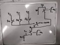
In my example circuit provided the main 120V switch is in Auto mode. When VR1 is energized node T17 is backfed 120VAC if someone forgot to open sw1 and sw2 now the load on t44 is running through the voltage backfeed.
I am looking for some suggestions to fix this issue as I assume it's a problem with switch placement that I'm not seeing. I don't really want to add 17 relays to isolate each switch.
The problem is the way it's currently connected if in Auto mode and two load switches are turned on one being a switch that isn't supposed to be on that load will then be supplied 120VAC.
In my example circuit provided the main 120V switch is in Auto mode. When VR1 is energized node T17 is backfed 120VAC if someone forgot to open sw1 and sw2 now the load on t44 is running through the voltage backfeed.
I am looking for some suggestions to fix this issue as I assume it's a problem with switch placement that I'm not seeing. I don't really want to add 17 relays to isolate each switch.
Attachments
-
 3 MB Views: 15


