20 Meter CW transmitter

Thread Starter

BrentM

Joined Oct 26, 2012
43
Hello Everyone,

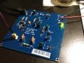
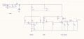
I have designed a CW transmitter operating at 14.06 MHz. It is a pretty simple design consisting of an oscillator, driver, and a power amplifier. Its a combination of different circuitry I found online and a bit of my own stuff. The goal here is to design a CW transmitter that can put out at least a Watt at this frequency with decent quality (no harmonics, chirp...etc). I have attached a picture of the schematic. I just wanted to share this design in an effort to get some feedback. What do you guys think of it? Do you see any potential issues? How can I improve it?

I plan on manufacturing a PCB for it at some point, but wanted to run the design by people smarter than myself.

Best Regards,

Brent
 

Attachments

Last edited:

alfacliff

Joined Dec 13, 2013
2,458
I would key the driver and output, less chirp that way. also, the diode across the output transistor isnt used in ham radio transmitters, it can cause harmonics. the output i net should be adjustable for resonance.
good luck.
 

Papabravo

Joined Feb 24, 2006
21,225
I would key the driver and output, less chirp that way. also, the diode across the output transistor isnt used in ham radio transmitters, it can cause harmonics. the output i net should be adjustable for resonance.
good luck.
I don't think it is an actual diode but a representation of an intrinsic diode in the device itself. As to the suitability of this device as a RF output transistor I have to wonder.

Wait a minute, the schematic symbols is for a FET but the almost unreadable note on the part number says BJT. So which is it and why would yo do such a cockamamie thing as using a FET symbol for a BJT? Most noobs on this board would never think of doing such a thing.
 

Thread Starter

BrentM

Joined Oct 26, 2012
43
I don't think it is an actual diode but a representation of an intrinsic diode in the device itself. As to the suitability of this device as a RF output transistor I have to wonder.

Wait a minute, the schematic symbols is for a FET but the almost unreadable note on the part number says BJT. So which is it and why would yo do such a cockamamie thing as using a FET symbol for a BJT? Most noobs on this board would never think of doing such a thing.
Lol. I used the FET symbol because it was the only component in the current library that used the TO-39 PCB footprint. I just forgot to change it back. I constructed the design on a breadboard for testing purposes and was actually surprised that it worked as well as it did. Using my shitty watt meter, I was getting about 1.5 Watts into a 50 ohm load. Surprisingly enough, there was very little chirp. I'm going to mess around with it and see if any of the suggested improvements make a difference.

Brent
 

upopads2

Joined Sep 20, 2014
54
Bro what are you using to supply the 12 V are you hooking up with a wall wart? if so do you know what kind of female connector hook up and then go to flying leads on your breadboard.

can you upload a sound wave of the crystal or are you copyrighting it?
 
Last edited by a moderator:

Thread Starter

BrentM

Joined Oct 26, 2012
43
Upo, it's powered by a 12VDC regulated power supply, and it connects to the board using a 2.5mm DC power connector.. If you would like to hear the received signal, I'll upload a sample this weekend.

Also, I'm not sure what you mean by copyright it? Can you explain?

Brent
 

Thread Starter

BrentM

Joined Oct 26, 2012
43
The prototype boards finally arrived. I ordered 5 boards but they accidently sent me 13. Great success.

I assembled one and tested it out. No noticeable chirp and nearly 500 mW of output power with the BC547 as a power amp (2N3053 still hasn't arrived yet). With the addition of the 2N3053, output power should be well over 1 Watt. I'm planning on producing more of these boards and selling them if anyone is interested.

Brent
 

Attachments

radiohead

Joined May 28, 2009
514
There are several RF transistors to choose from for an output amplifier (PN918, 2N4427, 2N3866, BLY series by Philips, 2N5109 (wide band AM) to name a few. There are also ICs designed for this job too (MAR or GALI series by microcircuits). One piece of advice: on your prototype, spread your components out to allow for heat dissipation and be sure to heat sink any power transistors to avoide damage or destruction. The most critical part of RF amplifier design is to ensure you have an antenna matching network or an antenna that has a low VSWR. If you have a mismatched antenna, you risk burning up your amplifier circuit in addition to significantly decreased transmit range. Check your local laws to see how much power you can legally push with0ut a license, you don't want to end up in the pokey. Licensed stations pay for their air time so they have all the rights, you are not paying so you have none.
 

alfacliff

Joined Dec 13, 2013
2,458
for use on the 20 meter band, you will have to have a general or extra class ham liscense. local has nothing to do with it, it is federal law.
 

Thread Starter

BrentM

Joined Oct 26, 2012
43
Thanks for the replies.

Radiohead, I basically adhered to your advice. I left plenty of space for heat dissipation and included an antenna matching network (LC Pi filter). I just installed the 2N3053. It's not a bad transistor, but it's also not the best. It puts out roughly 1.1 Watts into a 50 ohm load.
 

Thread Starter

BrentM

Joined Oct 26, 2012
43
Update:

I did a bit of redesign on the transmitter.

- The driver stage is keyed, instead of the oscillator. This eliminated the little chirp that was present.
- I added a couple of varactor diodes and a potentiometer to the oscillator to allow for frequency adjustment.
- I replaced the output transistor with a 2N3924. The power output increased to 1.4 Watts at 12V and 2 Watts at 15V.
- I re-manufactured the PCB to reflect the changes and placed the design in a aluminum enclosure.

Brent
 

Attachments

KL7AJ

Joined Nov 4, 2008
2,229
I'd concur that there may be a bit of chirp keying the oscillator directly...even though it's rockbound. You can key lower frequency crystals pretty well, but I think you might be reaching the edge on 20 meters. You'll have to try it and see.
 

alfacliff

Joined Dec 13, 2013
2,458
with a three stage transmitter, you could use lower frequency crystals and multiply in the driver. 40 meter crystals are usually cheaper than 20 meter, and sturdier too. higher frequency crystals get a bit thin.
 

Thread Starter

BrentM

Joined Oct 26, 2012
43
The chirp in the original design was minimal, but I'm picky and just wanted a more stable tone. Keying the driver did exactly that. I also used a PNP in the keying circuit, instead of the NPN I was using before. Now I've got an output signal that is most excellent. A nice, clean (and stable) sine wave at the output.

I'm not sure I'm really sold on the frequency mixing idea. The goal for this design was to build a simple transmitter, and I think the current design definitely embodies that. In my future transmitters, I will definitely look into it, though.

Thanks for the advice, guys.

Brent
 

alfacliff

Joined Dec 13, 2013
2,458
fequency mixing? I was refering to harmonics, like the second harmonic of 7 mhz is 14. back in the old days of ham radio, novices were required to use crystal control, and usihg harmonic crystals could save you quite a bit. later when VFO's came out, they were usualoly 160 meter oscilators, with their dials calibrated with harmonics since a band switch might cause drift.
 

ku4uv

Joined Oct 30, 2015
2
Lol. I used the FET symbol because it was the only component in the current library that used the TO-39 PCB footprint. I just forgot to change it back. I constructed the design on a breadboard for testing purposes and was actually surprised that it worked as well as it did. Using my shitty watt meter, I was getting about 1.5 Watts into a 50 ohm load. Surprisingly enough, there was very little chirp. I'm going to mess around with it and see if any of the suggested improvements make a difference.

Brent
Do you have an updated schematic of the final transmitter design? I really want to build one of these. Thanks!
 
Top