100 khz triangle wave generator..

Thread Starter

baggio2

Joined Dec 25, 2008
60
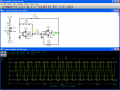
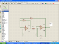
hi...i wanna generate 100 khz triangle wave and designed that circuit by using TL082 opamp . it works in simulation program but not in real..what is the problem?am i using wrong opamp? which opamp should i use if TL082 is wrong?
 

Attachments

Last edited:

SgtWookie

Joined Jul 17, 2007
22,230
I don't see how it worked; you don't have any Vcc or Vee supply to the opamp.

R5 is too low in value. I received a very distorted and clipped triangle wave when I simulated your circuit. Increase it to around 2k.
 

Wendy

Joined Mar 24, 2008
23,429
I tried something similar. I need to look a little closer. Let me study it and I'll get back with you. Meanwhile, you can take a look at my experiences, it didn't go too smoothly for me either at first, but I did figure it out.

http://forum.allaboutcircuits.com/showthread.php?t=12405

The 555 makes a nice Schmitt Trigger, which is half of what you've built. Yours is noninverting, which is good. What I need to calculate is the hysterisis voltages, this will determine what the amplitude of the triangle will be. What are your power supply voltages? Gee, I think Wookie said something similar...

R5 is 470Ω, and C3 is 0.4µF, correct? The others are 11KΩ and 10KΩ?
 
Last edited:

DickCappels

Joined Aug 21, 2008
10,187
If it works with a much larger capacitor as C3 (much lower frequency), then suspect the opamp. The unity gain bandwidth of an TL082 is only 3 MHz.
 

Wendy

Joined Mar 24, 2008
23,429
Just a quick redraw, to allow for easier readablility (and as a check).


I'm looking at hysterisis, I suspect it is way too wide. If the power supply is ±12VDC and the output is +12V, then it will take at least negative 10.9V to make it switch. It works this way for the other polarity too. This assumes the op amp can go rail to rail, a dubious proposition. Try reducing R7 to 4.7KΩ and see how it works.
 

Attachments

Last edited:

Thread Starter

baggio2

Joined Dec 25, 2008
60
Just a quick redraw, to allow for easier readablility (and as a check).


I'm looking at hysterisis, I suspect it is way too wide. If the power supply is ±12VDC and the output is +12V, then it will take at least negative 10.9V to make it switch. It works this way for the other polarity too. This assumes the op amp can go rail to rail, a dubious proposition. Try reducing R7 to 4.7KΩ and see how it works.
the most important thing in this circuit is frequency...i need 100 khz and i am using TL082...this opamp is enough for my circuit?? your circuit is 3 khz...
 

hgmjr

Joined Jan 28, 2005
9,027
In your simulation circuit you are using a dual power supply arrangement. Are you using a dual supply to power the real thing? If not then the circuit as drawn will not work.

hgmjr
 

Wendy

Joined Mar 24, 2008
23,429
So what are the real part values? Your diagram wasn't very clear, which is why I tried to redraw your schematic. You do need to drop R7, the good news is you get to use larger parts on C3/R5 to compensate.
 

SgtWookie

Joined Jul 17, 2007
22,230
I'm willing to bet that he's trying to use 9v transistor batteries without 100nF transient surpression caps between his Vcc/Vee pins and to ground.
 

Bernard

Joined Aug 7, 2008
5,784
Your triangle gen. is duplicate , except for some values, of AN20-10, National Semi. Application Hand book 1.1973. It shows R5 as 1.4k in series with 140k pot,for frequency control,R6 10k with 1M pot for amplitude.For 100k Hz C3 about 1.6 nF,@ R5 1k.
 

Thread Starter

baggio2

Joined Dec 25, 2008
60
ok i am gonna post full schematic...its frequency is 138 Khz according to
the formula and it is enough for me but doesnt work in real...is the problem TL082 or something else...? and my dual supply is a benchtop supply...
 

Attachments

Wendy

Joined Mar 24, 2008
23,429
I'm still curious as to what the parts are. For example, C1 is 4n7. What is that?

You're new hysterisis trigger point is 6.71V of 9V. That is 75%, which is better than the 91% trigger point.

Look at your voltages, the Schmitt Trigger is easy to tell if it is working or not. The other op amps should have the same voltage on both the inputs.


Attachments

Last edited:

hgmjr

Joined Jan 28, 2005
9,027
Bill,

4n7 is just another way of expressing 4.7 nanofarads.

However there is a bit of inconsistency since the 8.2 kilohm resistor should be written 8k2 if the convention is to be maintained.

hgmjr
 

Audioguru

Joined Dec 20, 2007
11,248
The opamp has a difficult time trying to drive R5 when it is as low as 470 ohms. The opamp will clip which distorts the waveform. Use a minimum of 2.2k for R5 and reduce the value of the capacitor to get the frequency back to 100kHz.

The TL081 has a voltage gain of only 30 at 100khz so the triangle-wave will be curved a little.
 

SgtWookie

Joined Jul 17, 2007
22,230
The opamp has a difficult time trying to drive R5 when it is as low as 470 ohms. The opamp will clip which distorts the waveform. Use a minimum of 2.2k for R5 and reduce the value of the capacitor to get the frequency back to 100kHz.

The TL081 has a voltage gain of only 30 at 100khz so the triangle-wave will be curved a little.
Yep, that's the basically the same track I started off with. Our OP was so slow in responding that I thought he was gone.

I simulated it using an LF353 model, which is the same as TI publishes for the TL082 and TL072. With a few mods, it looks pretty decent at 110kHz.

Simulation attached.
 

Attachments

Thread Starter

baggio2

Joined Dec 25, 2008
60
Yep, that's the basically the same track I started off with. Our OP was so slow in responding that I thought he was gone.

I simulated it using an LF353 model, which is the same as TI publishes for the TL082 and TL072. With a few mods, it looks pretty decent at 110kHz.

Simulation attached.

so will ur circuit work in real? becos my circuit is working in simulation too...anyway i better try it...thank you for ur help..
 
Top