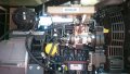
Greetings Everyone,
I am trying to control the Lever of a mechanical Diesel Pump. i Found a rotary actuator that operates 0-7 Ampere PWM which can control the lever of Mechanical diesel Pump. My control system sends a speed Up and Speed Down Pulse ( 2 Outputs) which energizes 2 relays to increase or decrease the speed of the Diesel Engine (Control the movement of lever). Please could any one help support with suitable Circuit to help operate the Rotary actuator by Just Closing a switch for Speed Up or closing a switch for Speed. there for as my controller sends a pulse and the Speed up relay energizes and its switch will close (Closing a switch in Suitable Circuit) and the speed of rotary actuator will increase same goes for speed down.
I am trying to control the Lever of a mechanical Diesel Pump. i Found a rotary actuator that operates 0-7 Ampere PWM which can control the lever of Mechanical diesel Pump. My control system sends a speed Up and Speed Down Pulse ( 2 Outputs) which energizes 2 relays to increase or decrease the speed of the Diesel Engine (Control the movement of lever). Please could any one help support with suitable Circuit to help operate the Rotary actuator by Just Closing a switch for Speed Up or closing a switch for Speed. there for as my controller sends a pulse and the Speed up relay energizes and its switch will close (Closing a switch in Suitable Circuit) and the speed of rotary actuator will increase
same goes for speed down.Attachments
-
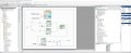
 59.3 KB Views: 15
 -
 79.2 KB Views: 13
 -
1.7 MB Views: 8