Radio Controlled Activation Unit

Thread Starter

frogy

Joined Dec 24, 2007
11
I've been working on a remote controlled activation unit.
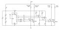
I now have removed and altered a radio controlled circuit from a small remote controlled car that is 40 MHz...

I have one main problems with this design...

The 40 MHz receiver has 2 outputs that are normally both high at .8 VDC.
I'll make a small table with O# as output and T# as trigger input logic (Button 1 and 2 on receiver).

The outputs are set this way to control forward\reverse on a motor...
Idle:
T1 || 0
T2 || 0
O1 || 0.8
O2 || 0.8

Triggered:
T1 || 1
T2 || 0
O1 || 1.5
O2 || 0/-1.5

T1 || 0
T2 || 1
O1 || 0/-1.5
O2 || 1.5

I'm planning on only using one trigger to activate the circuit... The Triggered stage of the receiver is fine, but having current during the idle state is confusing me.

Here's a few things I've been thinking about trying...
Voltage Comparator (339 \ similar)
O1 or static source to Reference (V-?)
O2 through diode (for forward drop) to Comparison (V+?)

Theoretically, the Reference which should be .8v should register larger than the .2v Comparison after a forward drop from a 4148 diode, but I'm not sure if a comparator can compare such low voltages.


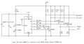
The circuit I'm trying to switch is pretty high voltage and can not use a mechanical relay (due to mechanical bounce).

I'm going to be using this circuit to fire an "electromagnetic metal accelerator":)D) with a few hundred\thousand volts and a few farads of capacitance. The load will be controlled by an IGBT or SCR, most likely a 2N6509G (lead free 2N6509 800V 25A SCR [high pulse rating]).
An 2N6509 requires 1-1.5v @ 9-30mA to trigger.


Here's the summary:
I need a Comparator or XOR gate to determine a button has been pressed on the transmitter (changes the outputs from both high, to only one high), then I need that signal to be amplified to 9-30mA to trigger the SCR.


This seems very simple to me, yet I cannot figure out why it's not working...
 

thingmaker3

Joined May 16, 2005
5,083
Theoretically, the Reference which should be .8v should register larger than the .2v Comparison after a forward drop from a 4148 diode, but I'm not sure if a comparator can compare such low voltages.
The LM339 should handle .2V I/P with no problem. Typical gain is 200.


Have you considered using both channels and some kind of code? This would reduce erroneous triggering from nearby RC hobbyists. Wouldn't want the thing to go off in your face just because the neighborhood kids were playing.:eek:
 

scubasteve_911

Joined Dec 27, 2007
1,203
Forgive my ignorance, but I was under the impression that RC recievers output a PWM signal, not a variable voltage. Are you sure you aren't measuring the average PWM through a volt meter?

For a really simple application, you can make a PWM to voltage converter via a suitable low-pass filter, then use a comparator to distinguish the levels.

Steve
 

Thread Starter

frogy

Joined Dec 24, 2007
11
I'm using the outputs that normally connect to a very small DC motor.

When T1 (Button 1 [Forward]) is pressed O1 turns from 0.8v to 1.5v and O2 changes from 0.8v to 0v...
When T2 (Button 2 [Reverse]) is pressed O1 turns from 0.8v to 0v and O2 changes from 0.8v to 1.5v...

Unless they used pulse-width modulation for a non-speed controlled motor, it would not output PWM....

PWM is normally used when speed-control is necessary, such as a more expensive R\C car in which the transmitter sends the pulses closes together for faster speed.

I do not have an oscilloscope to test if it's PWM at the moment though... Since I can't get it to work correctly, it most likely is...

I actually forgot what R\C car I took apart... It's actually a 40 MHz car that I have taken apart and modified... The transmitter has only about 100 solder points... 5 transistors, 16 resistors, 6 capacitors [disk], 1 capacitor [electrolyte], 4 NO Momentary, 2 leds, 1 diode, 1 crystal oscillator [40 680], 1 IC...

The oscillator is a HC49(/U) (oval-type) package and 40/40.68 MHz...

The IC labeled "SUPER CHIP SDTX2B", seems to be obsolete... and Japanese... It's a DIP14... I can find datasheets for an SCTX2B, which is also a DIP14 and has something to do with oscillators.


Can't I make a simply Low-Pass from an RC circuit?
 

KMoffett

Joined Dec 19, 2007
2,918
frogy

I played with one of these (27Mhz Zip-Zap), but it had 4 outputs... Froward, Back, Left and Right. The L/R outputs are open-collector/open drain. The F/B outputs are from an H-bridge. In idle the lower two transistors/mosfet's in the bridge are not driven, and there is probably a leakage path the causes them to float to 0.8v. Once you activate them they are driven to ~0v. Have you tried to add a pull down resistor between each of these outputs and common? In my project I used the L/R outputs with pull-up resistors, so didn't have to deal with that. Don't have it around anymore, or would try it myself.

Ken
 

Thread Starter

frogy

Joined Dec 24, 2007
11
Trying 1k pull-down resistors to common ground from both O1 and O2, there was still current on both during idle...

I did notice something different though... When pressing the forward trigger, O1 would lock at 1.2v and O2 at 0.5v, until the reverse trigger is pressed, after which O1 would lock at 0.5v and O2 at 1.2v, and vise versa...

The thing that surprises me is that the logic of which output was "locked" is kept even after power is removed...

What do you suggest as a pull down value?

The receiver and transmitter both do have L/R... The L/R terminals where connected to small inductors that worked as electromagnets to pull a small neodymium magnet towards which side the car was to steer. I ripped off the inductors, so I had to find where they were connected, but that was pretty easy...

I noticed that the L/R are open-collector/open-drain (like you said), and that the source/emitter is connected to ground... So they can easily sink current from the 1.5v battery to ground... Should make triggering the 1.5v SCR very easy...

Thank you very much for the help... (I think) My problems are solved :D
 

KMoffett

Joined Dec 19, 2007
2,918
frogy,

The 1K pulldowns are about wahat I'd have tried. Since both outputs are at the same potential at idle, no current flows through the motor, so no problem for the original car. It would be nice to work out the motor outputs, since the four combinational outputs could give you 9 possible conditions: F, B, R, L, F/R, F/L, B/R, B/L, and Idle. As in your original post using a diode, shottcky perhaps, in series with a resistor to the base of an NPN transistor might work. 0.8 v would not be enough forward bias the diode (0.3 Vf) and the transistor (0.6 Vbe), but the 1.5v would.

This is a "mind experiment" for me right now...but it might be worth a try...for future reference.

Ken
 

Thread Starter

frogy

Joined Dec 24, 2007
11
It seems confusing to me for some reason...

Here's my circuit minus the RF...


I'd like to test the motor terminals also, but atm I don't have any transistors with a Vbe below 3v.... I have a few each of the following: 2N5088, MPSA42, 2N4124, 2N4401, A733, C945, C9014, C9015... The lowest Vbe are the 5088's with 3.0v...

Multiple F/B/R/L would be harder to do... 2 outputs at once drains their output voltage quite a bit...

I may add a servo to raise\lower the coilgun, and possibly reload... That would be awesome...
 

thingmaker3

Joined May 16, 2005
5,083
I'd like to test the motor terminals also, but atm I don't have any transistors with a Vbe below 3v.... I have a few each of the following: 2N5088, MPSA42, 2N4124, 2N4401, A733, C945, C9014, C9015... The lowest Vbe are the 5088's with 3.0v...
Are you confusing Vbe-max with saturation Vbe? Vbe-sat for most of the transistors you listed is less than one volt.
 

Thread Starter

frogy

Joined Dec 24, 2007
11
Are you confusing Vbe-max with saturation Vbe? Vbe-sat for most of the transistors you listed is less than one volt.
Hahaha... Yes I was...

I'm not very familiar with datasheets


I don't really know what I'm doing here either...
I've got an NPN transistor that sinks power, but only about 1.5v 400mA

How do I activate another transistor with a ground?
If my load can be activated with 3.5v 20mA max (lets say blue led)
6v through 1k resistor to collector
0v to emitter

Normally I'd connect the saturation voltage to the base through a resistor, but since I have ground...

Do I connect V+ to the Collector and Base (through resistors) and V- to Emitter... Then I connect the sinking NPN from my receiver to the Base? That's basically a pulled-up inverter.
 

KMoffett

Joined Dec 19, 2007
2,918
Frogy,

Again, this is just a mind experiment on my part. The attached is a schematic of what I think might work...ince I don't have an opportunity to try this...:rolleyes:

I have done this with the L/R outputs, but not with the F/B. I didn't include any values because my pencil schematics are at work.

Ken
 

Attachments

KMoffett

Joined Dec 19, 2007
2,918
frogy,

I had a chance to play with the receiver for a 49MHz ZipZap car today. I wound up using the pull-down function of the motor F/B outputs instead of the pull-up, to convert to logic level outputs. My idea of diodes in series with these outputs didn't seem to work well. The 2N2484's are high beta (250-800) transistors. All the logic outputs are active high.

Ken
 

Attachments

Thread Starter

frogy

Joined Dec 24, 2007
11
I have the circuit working, but I was wondering if you could suggest a good pull-up value for the Left\Right transistors....


This is how I'm running the circuit, R1 and R2 are both 1k (R2 depends on load)

R1 is the pull-up transistor... It is going to be connected to 1.5v...


I am planning on extending the range of this circuit by adding a larger antenna to the receiver and adding more power\larger antenna to the transmitter...
 

KMoffett

Joined Dec 19, 2007
2,918
Frogy,

Your transistor should be a PNP not an NPN. Emitter to +V, collector to load, load to -V, R1 between +V and transistor's base (as shown), resistor R2 between LEFT and transistor's base...as in my schematic. Since R1 and the emitter will be going to the 1.25v +V in the receiver (not to +5v as in mine) and I don't know what your load is, I don't know the values for R1 or R2. What is the LOAD? Also the PCB layout is different than mine, so I can't be sure my values will work. I'll try it on mine tomorrow.

Ken
 

Thread Starter

frogy

Joined Dec 24, 2007
11
The load is going to be controlled by an SCR (the 2N6509) which requires 1.0-1.5v and 9-30 mA (to trigger)...

Really you didn't change anything with my circuit other than add a resistor between left and the base, and replace the transistor with a PNP (why?).

I was thinking my circuit was bad, due to the short circuit across the Collector and Emitter...

Really R2 isn't needed in this diagram...
 

KMoffett

Joined Dec 19, 2007
2,918
Frogy,

The reason for my PNP design is to power the load when the Left button is pushed. If it were done with a NPN, the Load would be powered "except" when the Left button was pushed. But...I don't quite understand your wiring diagram. The way you have your collector to +V and emitter to -V ,and you base biased ON through R1 to +V, it will short out +V to -V. You say that the LOAD is "controlled" by an SCR. Do you mean the load "controls" an SCR? Is the LOAD the SCR's gate/cathode input? Maybe you can include that part of your circuit.

Ken
 

Thread Starter

frogy

Joined Dec 24, 2007
11
Frogy,

Your transistor should be a PNP not an NPN. Emitter to +V, collector to load, load to -V, R1 between +V and transistor's base (as shown), resistor R2 between LEFT and transistor's base...as in my schematic. Since R1 and the emitter will be going to the 1.25v +V in the receiver (not to +5v as in mine) and I don't know what your load is, I don't know the values for R1 or R2. What is the LOAD? Also the PCB layout is different than mine, so I can't be sure my values will work. I'll try it on mine tomorrow.

Ken
I don't see how your circuit would work for a normally open collector... With V+ constantly to the base (until the LEFT is pushed) the transistor would be held closed. That would give me a normally closed connection until the button is pushed.

I rarely every use PNP transistors, nor have studied them, but I'm pretty sure that your right though. Instead of an NPN where it switches while the base is high, does a PNP switch while the base is low?

It's pretty obvious that the SCR is the load controller for the "electromagnetic metal accelerator"...
 

KMoffett

Joined Dec 19, 2007
2,918
I don't see how your circuit would work for a normally open collector... With V+ constantly to the base (until the LEFT is pushed) the transistor would be held closed. That would give me a normally closed connection until the button is pushed.

I rarely every use PNP transistors, nor have studied them, but I'm pretty sure that your right though. Instead of an NPN where it switches while the base is high, does a PNP switch while the base is low?

It's pretty obvious that the SCR is the load controller for the "electromagnetic metal accelerator"...
1. The key to turning on the PNP transistor (Q4) is the voltage drop across the 1K (R5) resistor. If this voltage, the voltage from base to emitter, is less than 0.6V it is off and the voltage across the collector resistor in zero. If the base-emitter voltage is greater than 0.6v, it is turned on and the drop across the collector resistor is about equal to +V. In my circuit R5 +R11 form the load resistance for the receiver's LEFT open-collector output. Change in voltage across this causes a change in voltage across R11 and Q4's base-emitter, switches Q4 on or off, and the voltage across R9 to change between zero and +5v.

2. Yes! PNP's work, polarity wise, just the opposite of NPN's. Emitter to +V, collector to load, load to -V, base-emitter voltage (ref to -V) higher than (+V)-(0.6v) turns the transistor off, and base-emitter voltage lower than (+V)-(0.6v) turns the transistor on.

A quick tutorial:
http://www.kpsec.freeuk.com/trancirc.htm

3. Nothing is obvious in a circuit I haven't seen. :confused: Can you draw the circuit that shows exactly how you intend to connect the SCR to the driver transistor to the R/C receiver.

The devil's in the details. ;)

Ken
 
Top