Facebook
 Google
 GitHub
 Linkedin
Perpetual Back and Forth Circuit
I am trying to design a perpetual back & forth circuit to run a 12 volt trolley on a single HO track. I actually created a design of a circuit 3 years ago and eventually built it. It did NOT work - hence my appearance here!
Any help with this hobby obsession of mine will be greatly appreciated.
I will start with the requirements and then give what I have attempted along with photos attached (as PDFs).
Requirements :
-------------------------------------------------------------------------
A) DC Only (no DCC) - track polarity will be reversed to reverse trolley (Street Car if in Nawlins).
B) Track will be 2 rails and can be any length - it will have a "dead end" on each end (this is NOT a loop).
C) Power applied to track using only 2 wires (no other wires connected to track).
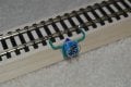
D) There will be a gap on the starboard side rail at both ends of the track. This will be bridged with a diode which will stop the trolley until the polarity is reversed.
E) Voltage applied to the two wires will be nominal 12 volts (or more if using HO power pack and speed setting).
F) Trolley should travel past the gap and stop. After current consumption has stopped and waiting a specific time, the polarity should be reversed.
G) Trolley will travel in the opposite direction and once past the other gap will stop. After current consumption has stopped and waiting a specific time, the polarity should be reversed.
H) Some time delay is needed once trolley has stopped - do not want to throw the motor in full reverse when running (this is noted in steps F and G).
I) This will run indefinitely until the power is removed from the circuit (turned off).
-------------------------------------------------------------------------
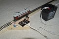
I have built a test track (see attached pictures) which implements a manual version using a double-poll double-throw knife switch (wired as cross-over). When the switch is dropped to the left - the trolley travels to one end and past the diode gap at which point it stops. If the switch is flipped to the right - the trolley travels in the opposite direction until the other diode gap is passed. This test board test track proves the concept of the diode gaps and polarity reversing. It has a two wire terminal strip so the "new" reversing circuit can be plugged in (and replacing the knife switch).
Attachments :
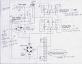
Perpetual B&F.pdf - original design with suggestion of substitution of optoisolators. This was actually built (not with optoisolators) and when power applied - it buzzed like an electric razor. I believe the problem is in the 2 latching relays - they may be flipping each other back and forth.
Double Latching Relay for Reversing.pdf - this is my logical view of how I intended the 2 latching relays to operate the polarity reversal. This part needs some delay or isolation - I have not bread boarded this piece but I think it is a problem.
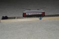
Test Track.pdf - contains pictures of the test track and trolley along with the gaps and diodes. When the trolley passes a gap and stops, the switch is thrown and the trolley travels in the opposite direction until it hits the other gap.
-----------------------------------------------------------------------
Here is what I think I need : 3 major portions of the circuit.
1st is the reversing portion (see Double Latching Relay for Reversing.pdf) which fired from a momentary voltage. I wanted to do this with 2 coil latching relays (I bought a bunch from D.K. - see the B&G picture for part numbers).
2nd is the current sensing portion. I got the original idea from neighbor's model railroad layout. He used a bridge rectifier and Christmas lights to trigger a photocell. I substituted LED's (one for each direction) based on findings from the web. My original design did not account for any delay. The photocell was supposed to pull the SPDT relay in when the trolley was running. The absence of the current would make the LED's go out causing the relay to fall and send the momentary voltage to the latching relays. This would cause the polarity to switch, the trolley to run, the LED's to light pulling the SPDT relay on. This whole thing was "kinda" electro-mechanical. I think a 555 timer might be better suited (more on that in 3rd part). I also showed some optoisolators on my original drawing (with part numbers). I bought a bunch of these on my last Digikey order. I got the DC and AC versions - The AC version will detect in both directions. The DC versions are for future block detection activities in another layout. I would like the circuit to use those if possible (instead of the photo cell and lights).
3rd part is to "Invert" the absence of current on the tracks in order to "fire" the 2 latching relays. From what I have found trolling the websites - 555 timer circuits may be the trick for this. I don't know enough about interfacing multiples of these but I have read up on the different implementation favors of the 555 timers. I also figured this is where I might be able to add some timing and delay.
--------------------------------------------------------------------
I have thrown a lot out there for my first post hoping to be as detailed as possible. Please ask for clarifications if needed.
I have never posted to a forum before but after reading through tons of posts and the great answers some of your members provided - I couldn't resist.
My profession is software applications design. I have done some dabbling in electronics over the years.
Thanks in advance for any help your members can provide to me in figuring this out.
Joe
I am trying to design a perpetual back & forth circuit to run a 12 volt trolley on a single HO track. I actually created a design of a circuit 3 years ago and eventually built it. It did NOT work - hence my appearance here!
Any help with this hobby obsession of mine will be greatly appreciated.
I will start with the requirements and then give what I have attempted along with photos attached (as PDFs).
Requirements :
-------------------------------------------------------------------------
A) DC Only (no DCC) - track polarity will be reversed to reverse trolley (Street Car if in Nawlins).
B) Track will be 2 rails and can be any length - it will have a "dead end" on each end (this is NOT a loop).
C) Power applied to track using only 2 wires (no other wires connected to track).
D) There will be a gap on the starboard side rail at both ends of the track. This will be bridged with a diode which will stop the trolley until the polarity is reversed.
E) Voltage applied to the two wires will be nominal 12 volts (or more if using HO power pack and speed setting).
F) Trolley should travel past the gap and stop. After current consumption has stopped and waiting a specific time, the polarity should be reversed.
G) Trolley will travel in the opposite direction and once past the other gap will stop. After current consumption has stopped and waiting a specific time, the polarity should be reversed.
H) Some time delay is needed once trolley has stopped - do not want to throw the motor in full reverse when running (this is noted in steps F and G).
I) This will run indefinitely until the power is removed from the circuit (turned off).
-------------------------------------------------------------------------
I have built a test track (see attached pictures) which implements a manual version using a double-poll double-throw knife switch (wired as cross-over). When the switch is dropped to the left - the trolley travels to one end and past the diode gap at which point it stops. If the switch is flipped to the right - the trolley travels in the opposite direction until the other diode gap is passed. This test board test track proves the concept of the diode gaps and polarity reversing. It has a two wire terminal strip so the "new" reversing circuit can be plugged in (and replacing the knife switch).
Attachments :
Perpetual B&F.pdf - original design with suggestion of substitution of optoisolators. This was actually built (not with optoisolators) and when power applied - it buzzed like an electric razor. I believe the problem is in the 2 latching relays - they may be flipping each other back and forth.
Double Latching Relay for Reversing.pdf - this is my logical view of how I intended the 2 latching relays to operate the polarity reversal. This part needs some delay or isolation - I have not bread boarded this piece but I think it is a problem.
Test Track.pdf - contains pictures of the test track and trolley along with the gaps and diodes. When the trolley passes a gap and stops, the switch is thrown and the trolley travels in the opposite direction until it hits the other gap.
-----------------------------------------------------------------------
Here is what I think I need : 3 major portions of the circuit.
1st is the reversing portion (see Double Latching Relay for Reversing.pdf) which fired from a momentary voltage. I wanted to do this with 2 coil latching relays (I bought a bunch from D.K. - see the B&G picture for part numbers).
2nd is the current sensing portion. I got the original idea from neighbor's model railroad layout. He used a bridge rectifier and Christmas lights to trigger a photocell. I substituted LED's (one for each direction) based on findings from the web. My original design did not account for any delay. The photocell was supposed to pull the SPDT relay in when the trolley was running. The absence of the current would make the LED's go out causing the relay to fall and send the momentary voltage to the latching relays. This would cause the polarity to switch, the trolley to run, the LED's to light pulling the SPDT relay on. This whole thing was "kinda" electro-mechanical. I think a 555 timer might be better suited (more on that in 3rd part). I also showed some optoisolators on my original drawing (with part numbers). I bought a bunch of these on my last Digikey order. I got the DC and AC versions - The AC version will detect in both directions. The DC versions are for future block detection activities in another layout. I would like the circuit to use those if possible (instead of the photo cell and lights).
3rd part is to "Invert" the absence of current on the tracks in order to "fire" the 2 latching relays. From what I have found trolling the websites - 555 timer circuits may be the trick for this. I don't know enough about interfacing multiples of these but I have read up on the different implementation favors of the 555 timers. I also figured this is where I might be able to add some timing and delay.
--------------------------------------------------------------------
I have thrown a lot out there for my first post hoping to be as detailed as possible. Please ask for clarifications if needed.
I have never posted to a forum before but after reading through tons of posts and the great answers some of your members provided - I couldn't resist.
My profession is software applications design. I have done some dabbling in electronics over the years.
Thanks in advance for any help your members can provide to me in figuring this out.
Joe
Attachments
-
913.6 KB Views: 118
-
599.8 KB Views: 97
-
4.7 MB Views: 75
Last edited:
")