Mosfet circuit question - solar design conundrum

Thread Starter

russpatterson

Joined Feb 1, 2010
353
Hi There,

I've got a problem for a solar project which is: I need to turn the panel off if the battery is nearing overcharge, however I need the panel to be on if the battery, and the MCU (PIC in this case), are dead. I've been through a few circuits (and burned up a PIC or two) but I think I have a solution.

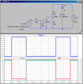
Does this schematic look legit?

http://backyardsolar.blogspot.com/2010/01/n-channel-mosfet-panel-solution.html

I'm new to MOSFETs and appreciate any insights. I'd be interested in any other designs for this kind of thing if you know about one.

This design does suffer from the drawback of overcharging the battery if the MCU side of things fails for any reason (voltage regulator, software etc.) which is not the best but seems better than a solar device that can't work once the battery is dead.

Thanks!
 

MikeML

Joined Oct 2, 2009
5,444
Several problems with yours. Here is one that works. Keeps the gate voltage at 10V. Will default to the ON state if the PIC dies as long as the PIC dies in a mode where its Port pin is HiZ or Low.
 

Attachments

Last edited:

Thread Starter

russpatterson

Joined Feb 1, 2010
353
Thanks for the reply. I do only switch on the negatvie side of the panel. The positive side is always connected to the battery. Sorry for the confusion, that's just a section of the schematic for the whole project.

I use that positive side voltage to turn the MOSFET on. So if the panel has voltage; it's switched on and current flows to the battery. I can turn the MOSFET off by setting an I/O pin on the MCU high, which will cause the gate on the mosfet to sink to ground and turn off. If the MCU pin is low or high z then the MOSFET is controlled by the panel voltage.
 

eblc1388

Joined Nov 28, 2008
1,542
Will default to the ON state if the PIC dies as long as the PIC dies in a mode where its Port pin is HiZ or Low.
Of course Murphy would no doubt make sure the PIC die outputting HIGH. :D

A capacitor in the signal path comes to mind....

If the PIC fails for whatever reasons, the output pulses will stop and the battery will be connected to solar panel direct. However, make certain that one does not use PIC INTERRUPT to perform the pulse output or else it is possible that the PIC program is stuck somewhere in la-la land but with the interrupt still working.


Attachments

Last edited:

MikeML

Joined Oct 2, 2009
5,444
L.Chung,

Wouldn't you just use the WatchDog timer mechanism built-in to the PIC rather than building an analog version into the port pin?
 

eblc1388

Joined Nov 28, 2008
1,542
Wouldn't you just use the WatchDog timer mechanism built-in to the PIC rather than building an analog version into the port pin?
How would the WatchDog can be of help if the PIC port pin is permanently stuck at high, due to part internal failure or external failed voltage regulator?
 

Thread Starter

russpatterson

Joined Feb 1, 2010
353
Thanks for all the replies. I'm not sure I can handle all the potential failure cases. I'm most concerned with the dead battery case. In that case, assuming the PIC and voltage regulator etc. are still functional then there is no way that the I/O pin could be left at high since there's no voltage on the PIC, correct?

MikeML, I see the voltage divider to get the gate voltage to ~10V. So that's to keep the gate voltage to a friendly level? What's the purpose of R4?

Thanks!
 

MikeML

Joined Oct 2, 2009
5,444
... I see the voltage divider to get the gate voltage to ~10V. So that's to keep the gate voltage to a friendly level? What's the purpose of R4?
Yes, the voltage divider keeps the Gate at ~10V, which is high enough to turn on the FET, but less than the gate breakdown voltage of about 20V.

R4 guarantees turn off of Q1, even with a floating or weakly pulled-up PIC port.
 

Thread Starter

russpatterson

Joined Feb 1, 2010
353
I'm new to MOSFET's but I thought that the VGS(th) represented the difference between the gate voltage and the source voltage. So the Gate voltage would need to be from 2 - 4 volts of the Source voltage. Since my mosfet is on the low side then the gate voltage will always be higher. So keeping it down to 10 volts is probably a good idea.
 

rjenkins

Joined Nov 6, 2005
1,013
The conventional way of preventing overcharge is a simple shunt regulator across the panel to prevent the battery voltage exceeding it's maximum full charge level, eg. somewhere around 13.8 - 14.5 for a 12V lead-acid or about 1.45 - 1.5V per cell for NiMH.

Any 'active' system must be taking some power from the battery, while a shunt reg only draws power when there is excess from the solar panels.

[The KISS principle: 'Keep It Simple, Stupid']
 

Thread Starter

russpatterson

Joined Feb 1, 2010
353
Hi rjenkins,

Thanks for the reply. I'm all for keeping it simple. However I already have an MCU on the device. I'm building a controller for a 500-600 GPH garden fountain. So there's the motor controller, different modes for the fountain, etc. So I've already got the MCU running and I only apply power to turn disconnect the panel ground from the battery. The other issue is that all the off-the-shelf controllers I've used are pretty bad when it comes to handling the battery low voltage case. They tend to switch on and off every few seconds and cause your attached device to wear out quickly. With the MCU I can know when the battery is actually ready run the device.

I looked around for shunt regulator circuits and it looks like you'd use a zener to sense the voltage then run the current through a big resistor instead of the battery. I like the idea of just disconnecting the panel rather than adding a big resistor that heats up.
 

spinnaker

Joined Oct 29, 2009
7,830
Hey Russ,

I am watching this thread because we have the exact same project. But I have not even started yet,

I'm just a newb but would be happy to share whatever I come up with. And please keep us posted on what you come up with.

One thought I had was to use an off the shelf battery charger and an off the shelf LED driver like the buck puck and have the PIC control it all.
 

Thread Starter

russpatterson

Joined Feb 1, 2010
353
Hey Russ,

I am watching this thread because we have the exact same project. But I have not even started yet,

I'm just a newb but would be happy to share whatever I come up with. And please keep us posted on what you come up with.

One thought I had was to use an off the shelf battery charger and an off the shelf LED driver like the buck puck and have the PIC control it all.
Hi Spinaker,

So you're building a fountain controller too? Check out my blog http://backyardsolar.blogspot.com/

I went through the off the shelf charge controllers and the problem I had was the way they handled the low battery voltage case. In my case I put a PWM motor controller in to control the pump so I could match the current being produced by the panel.
 

spinnaker

Joined Oct 29, 2009
7,830
Hi Spinaker,

So you're building a fountain controller too? Check out my blog http://backyardsolar.blogspot.com/

I went through the off the shelf charge controllers and the problem I had was the way they handled the low battery voltage case. In my case I put a PWM motor controller in to control the pump so I could match the current being produced by the panel.
THANK YOU THANK YOU!!! This is exactly what I was looking for!!!

I really should read your whole blog and ask questions later but I should get back to my real job and will ask some quick question if you don't mind. Hopefully you are still around to answer. :)

1. What made you pick 19K resistors as your current limiters in your mosfet switch?


2. How did you handle charging the battery? DO you just shut it doen at over charge? Or do you regulate it.

3. What did you use to drive the LEDs?

4. What did you use as a regulator for the mcu?
 

Thread Starter

russpatterson

Joined Feb 1, 2010
353
Hi there,

1) I need to go back and figure some better values. I just tested with 19K resistors and it worked. MikeML suggested some different values previously in this thread. 10K to the BJT and a voltage divider across the gate to the MOSFET to hold that at 10V.

2) I just apply the panel current/voltage to the battery until I get to 13.8 volts the turn off the panel, (or the current that is left over after the pump has used it's share). I'm learning about this as I do it so keep that in mind. I've read some articles about different charging stages for the different types of batteries (lead acid, lithium ion, etc.) but I have not implemented any of those types of smart chargers. I would like to do the smart charger in a future version. However I used an 8 pin PIC to keep costs down and I'm out of available pins for things like current monitoring. This depends on not hooking up a panel array that will kill the battery by producing too much current. In my case I know the panel that will be connected.

3) I just use a single, simple, status LED and limit the current with a resistor and drive it with an IO pin. What are you planning to use the LED's for? Lighting?

4) I don't recall the part number off the top of my head but I just picked a 5V voltage regulator that could take the high voltage coming off the panel. In most cases it will only get to 13.8V since I disconnect the panel after that. I've run it without a battery and connected a bunch of 4700uF caps in parallel just so I could start my pump motor. The voltage regulator did ok with the high voltage (~23V) but it got hot so it might not last if used like that.
 

spinnaker

Joined Oct 29, 2009
7,830
Hi there,


2) I just apply the panel current/voltage to the battery until I get to 13.8 volts the turn off the panel, (or the current that is left over after the pump has used it's share). I'm learning about this as I do it so keep that in mind. I've read some articles about different charging stages for the different types of batteries (lead acid, lithium ion, etc.) but I have not implemented any of those types of smart chargers. I would like to do the smart charger in a future version. However I used an 8 pin PIC to keep costs down and I'm out of available pins for things like current monitoring. This depends on not hooking up a panel array that will kill the battery by producing too much current. In my case I know the panel that will be connected.

Sorry to be so dense, but except for the MosFET switch, the panel is connected direct to the battery?

And you have a blocking diode right?

3) I just use a single, simple, status LED and limit the current with a resistor and drive it with an IO pin. What are you planning to use the LED's for? Lighting?
Yeah I thought you were doing a pump and a light?

I have an old LED light that has 108 LEDs. There are 36 parallel sets of 3 LEDs in series. I will probably be removing a few.

I went with one of these to drive the lights. It has a 5VDC supply for PICs.


4) I don't recall the part number off the top of my head but I just picked a 5V voltage regulator that could take the high voltage coming off the panel. In most cases it will only get to 13.8V since I disconnect the panel after that. I've run it without a battery and connected a bunch of 4700uF caps in parallel just so I could start my pump motor. The voltage regulator did ok with the high voltage (~23V) but it got hot so it might not last if used like that.
A 7805 by chance? That is a linear. Pretty inefficient for solar projects from what I understand. Wasted energy that could be going to charge your battery.
 
Top