Using Solid State Relay to Light up a Bulb

Thread Starter

raziiq

Joined Dec 15, 2008
35
Hi there.

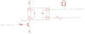
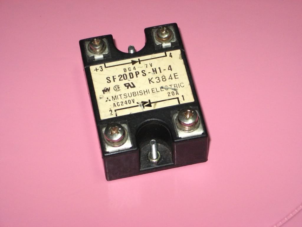
I have got this Solid State Relay , and i wanna make a circuit so that i can use this relay to take an input of 5V and give me an output of 110V (enough to lightup a bulb of almost 60WATT).


What else do i need to make this circuit?

BTW i have heard that breadboards are not a good choice to deal with high voltage, what should be the choice then?
 

Von

Joined Oct 29, 2008
65
Not much more.

When you connect your 5vdc power supply to terminals 3 & 4 (positive on #3), terminals 1 & 2 will conduct 100vac.

Wire the relay output in series with the light bulb and your 110 vac source.

No breadboard is recommended here. Use insulated crimp-on terminals to connect to the relay terminals.

Find a local electrician, electrical supply store, appliance repairman, air conditioning repairman. etc., he will likely give you advice for free.
 
Last edited:

BMorse

Joined Sep 26, 2009
2,675
You will need a couple more things besides the Lamp and the Solid state Relay, You will also need to fuse the line coming in to the SSR from the AC HOT, and also a switch to turn the +5 off when the lamp needs to be turned off....

I attached a simple sketch on how the components should connect to the SSR....

MAKE SURE YOU UNDERSTAND THE SAFETY ISSUES REGARDING WORKING WITH MAINS POWER!! IF YOU DO NOT UNDERSTAND SOMETHING, I SUGGEST CONSULTING A QUALIFIED TECHNICIAN....


My .02
 

Attachments

Thread Starter

raziiq

Joined Dec 15, 2008
35
I have found this link here and this is exactly what i am trying to do

http://www.glacialwanderer.com/hobbyrobotics/?p=9

But the thing is i cant understand why he is using another 5V at the upper part? Isnt the Circuit getting the power from Arduino?

Another thing is that how to put this schematic into real world example? Any beginners example on how to put schematics to real circuits?
 

BMorse

Joined Sep 26, 2009
2,675
I have found this link here and this is exactly what i am trying to do

http://www.glacialwanderer.com/hobbyrobotics/?p=9

But the thing is i cant understand why he is using another 5V at the upper part? Isnt the Circuit getting the power from Arduino?

Another thing is that how to put this schematic into real world example? Any beginners example on how to put schematics to real circuits?

Okay, here is a revised circuit for controlling the SSR with a uC (Microcontroller) - When you supply a logic High (Set output pin to 1) you will turn on the SSR, when a Logic low is supplied (set output pin to 0) the SSR will turn off......

Most uC projects I have seen (or done) it is almost a "standard" to switch on the low side than the high side of the circuit....

My .02
 

Attachments

BMorse

Joined Sep 26, 2009
2,675
Here is an example (I built it) of how SSR's would be in a "real world" circuit.... with the kind that you have, it is too large and bulky to be placed on a PCB or in circuit, those are designed more for running wires to and from them.....


and sometimes they can be smaller.....


My .02
 

Wendy

Joined Mar 24, 2008
23,429
I've used similar myself. They are extremely low power, the exact current depends on your SSR. You might want to measure it with an current meter, my rough guess is around 1ma.

As a guess, you probably don't need a transistor, just a logic level that goes between +5VDC and 0V. I could be wrong, but these suckers have been driven from the parallel port with ease.

The fuse is a must, and these suckers handle light bulbs and heaters well, motors are a bit more problematic.
 

Thread Starter

raziiq

Joined Dec 15, 2008
35
Okay, here is a revised circuit for controlling the SSR with a uC (Microcontroller) - When you supply a logic High (Set output pin to 1) you will turn on the SSR, when a Logic low is supplied (set output pin to 0) the SSR will turn off......

Most uC projects I have seen (or done) it is almost a "standard" to switch on the low side than the high side of the circuit....

My .02
Thanks for the reply and the diagram. In your diagram you are also using a 5V power Supply, but i have heard that if u r using a SSR u can get the power supply from the USB microcontroller also like Arduino, is it right?

Another things is what is AC_HOT?? is it Live AC? And what is F1? Sorry i am new to all this stuff
 

Thread Starter

raziiq

Joined Dec 15, 2008
35
BTW for this Circuit i have these following things, are they enough?

1) SSR MITSUBISHI SF20DPS-H1-4  IN: DC4~7V OUT: AC240V

2) 1N4004 Diode --> 1N4006 (1A 800V)

3) 2N2222 Transistor

4) 1K Resistor. (BTW which resistor will be best, i have got a bunch of resistors )

  • 1/4W Carbon:
  • 1/2W Carbon:
  • 1W Metal:
  • 2W Metal
Do i need something else to make this circuits? I am planning to connect this to Arduino board?
 

BMorse

Joined Sep 26, 2009
2,675
Thanks for the reply and the diagram. In your diagram you are also using a 5V power Supply, but i have heard that if u r using a SSR u can get the power supply from the USB microcontroller also like Arduino, is it right?

Another things is what is AC_HOT?? is it Live AC? And what is F1? Sorry i am new to all this stuff

Yes, AC_Hot would be the "Live" AC line (Black), and Neutral would be the return (White)....

F1 stands for Fuse 1, this is an inline fuse for the "Live" side of the AC power....

If the Arduino is 5 volt powered then yes, you can tap off of it for the 5 volts for the SSR....

My .02
 

BMorse

Joined Sep 26, 2009
2,675
BTW for this Circuit i have these following things, are they enough?

1) SSR MITSUBISHI SF20DPS-H1-4  IN: DC4~7V OUT: AC240V

2) 1N4004 Diode --> 1N4006 (1A 800V)

3) 2N2222 Transistor

4) 1K Resistor. (BTW which resistor will be best, i have got a bunch of resistors )

  • 1/4W Carbon:
  • 1/2W Carbon:
  • 1W Metal:
  • 2W Metal
Do i need something else to make this circuits? I am planning to connect this to Arduino board?
1/4 watt 220 Ohm should work.....

2N2222 should also work to replace 3904, but since you are connecting that to the arduino, you should be able to just by pass the whole transistor and connect the resistor from the arduino pin to the SSR's (-) input and just tie the +5 to the arduino power.....

Diode, you don't need, that is just a symbol on the SSR showing polarity of the LED in the optocoupler circuit in the SSR....


My .02
 

Thread Starter

raziiq

Joined Dec 15, 2008
35
1/4 watt 220 Ohm should work.....

2N2222 should also work to replace 3904, but since you are connecting that to the arduino, you should be able to just by pass the whole transistor and connect the resistor from the arduino pin to the SSR's (-) input and just tie the +5 to the arduino power.....

Diode, you don't need, that is just a symbol on the SSR showing polarity of the LED in the optocoupler circuit in the SSR....


My .02
Thanks for reply.

I heard Diode can be safe to use in your circuits as it will avoid any back currents to your delicate devices like Arduino, is it right?

BTW what is the purpose of Transistor if i use it in this circuit? And what difference it will make if i dont use it?
 

Wendy

Joined Mar 24, 2008
23,429
Unlike a regular relay, this circuit uses an LED lighting up a phototriac. This is why it takes so little power.
 

Wendy

Joined Mar 24, 2008
23,429
Depends on how much current you're SSR takes on the input. Like I said earlier, I'd measure it to see if it falls within the Arduino's specs. If it doesn't you'll need the transistor circuit discussed earlier.
 

Wendy

Joined Mar 24, 2008
23,429
I'm talking current, you're talking voltage. They both matter, but we don't know current. The innards of a SSR is a simple LED and resistor on the input side.
 

Thread Starter

raziiq

Joined Dec 15, 2008
35
Arduino pin delivers 40mA of current, i think it should be ok to use with SSR, or should i somehow calculate the amount of current required for SSR to operate?
 

BMorse

Joined Sep 26, 2009
2,675
Arduino pin delivers 40mA of current, i think it should be ok to use with SSR, or should i somehow calculate the amount of current required for SSR to operate?

Yes, do that, see how much current it takes to operate and see if it is within 40mA or less.... if more than 40mA, then use the transistor in the circuit.
 

Thread Starter

raziiq

Joined Dec 15, 2008
35
Do you recommend any component in between the SSR and Arduino? Like Resistor or Transistor, in order to avoid damage to Arduino? And if i add 1 or 2 more relays to Arduino's other Pins like 11 and 12, would it make any difference?
 
Top