Would using a relay work in this situation?

Thread Starter

Gibling

Joined May 28, 2009
11
Ok, so I don't really know a whole lot about circuits so I'm probably asking some really basic questions.

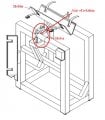
I work for a company that analyzes oil samples. We want one of our machines to mix the samples by rotating oil containers from horizontal to vertical, back to horizontal, to vertical in the other direction, and then back to horizontal. This process should repeat itself until the machine is turned off. We'd rather not use mechanical parts like toggle switches because we don't want the machine to break down over night when no one is there.

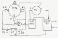
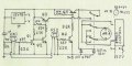
So would something like a time delay relay be plausable? Like you'd set the time, plug the machine in so the motor starts to rotate one way, then when the time is up, the motor rotates the other way. Can a relay do this? I'm guessing it would have to be DPDT and have a repeat cycle. Is there anything else you guys would suggest that might work better, even if it is mechanical? Thank you!
 

Wendy

Joined Mar 24, 2008
23,429
Short answer is yes. You can also use solid state parts, such as Solid State Relays. What is your power source? (Hz, Voltage, AC/DC)
 

Thread Starter

Gibling

Joined May 28, 2009
11
Alright bear with me here haha. We're in Canada so frequency is 60Hz? Were using a DC motor so we have a DC speed control which takes in AC 115 and outputs DC 90.

Would this be a suitable product to buy?
http://www.alliedelec.com/Search/ProductDetail.aspx?SKU=8190005&MPN=TR-63122

As you can tell, I'm a complete noob at this. This may be a bit much to ask but would someone be able to show me how the 8 pin octal setup works? Like which wires to connect to which pin? Or possibly draw a diagram? Basically where do I connect the two wires from both the motor and the speed control, and do I connect or cross or do anything to any other part?

Thank you so much guys, I really appreciate it!
 

Bernard

Joined Aug 7, 2008
5,784
Does this motorized rocker exist now? Do you know motor wattage or current draw? Without use of mechanical switches, would a photo-optical position sensor be allowed? A DP-DT relay might be helpfull for motor direction reversal, but it will require some logic circuits to control it. The speed control would be used in conjunction with the " black box".
 

KMoffett

Joined Dec 19, 2007
2,918
mix the samples by rotating oil containers from horizontal to vertical, back to horizontal, to vertical in the other direction, and then back to horizontal.
Is there a pause between each quarter turn? Could the rotation be in one direction, say clockwise:...top up...stop...top right...stop...top down...stop...top left...stop...top up...stop?

Ken
ken
 

Thread Starter

Gibling

Joined May 28, 2009
11
This looks like a job for a stepper motor.
I never thought of that. Though we're dealing with fairly heavy, highly compressed cylinders here. The cylinders themselves are around 30-40 lbs and the metal holster which the cylinder is strapped on to is probably another 20 lbs. Can a stepper motor handle these weights? I've only ever played around with the ones people use for robots and whatnot.

Does this motorized rocker exist now?
Yes, currently it uses a toggle switch to reverse the motor. We want to use something with less chance of slipping/getting stuck/breaking down because we may need to leave the rocker on overnight.

Do you know motor wattage or current draw?
Here is the motor we are using.
Here is the DC Speed Control.

Without use of mechanical switches, would a photo-optical position sensor be allowed?
Yes! My supervisor (I'm a work term student by the way) mentioned that this would be the ideal setup, and I searched for DPDT optical switches but couldn't find anything close. If you have anything in mind that could accomplish the task, then by all means, share with me!

Is there a pause between each quarter turn?
Currently no, and ideally not. I probably could have explained the rotation in a less complicated way...

Could the rotation be in one direction.
No, and for two reasons: 1) Safety. The cylinders containing the oil/gas can be very highly pressurized and having them upside down is not recommended. 2) We need to connect instruments like thermometers to the cylinder and the wires would get tangled if it was constantly rotating.

Thanks for everything so far guys!
 

Bernard

Joined Aug 7, 2008
5,784
Here is a block diagram of what we think you want.' assume there is further gear reduction to load. HR,HL & V are reflective, or beam break photo-optical sensors.FF is a R-S flip-flopto control DP-DT relay for motor direction. SSTD, might not be needed now, but would provide soft stop for motor, might eliminate sensor 'V" as no pause needed at vertical. D1,D2 represent short delays to allow SSTD, solid state time delay to break motor current rather than DP-DT relay.Speed control goes in any motor lead , inc. supply lines.
 

Attachments

R!f@@

Joined Apr 2, 2009
9,918
May be I can make you a set up.

Answer me these questions.
1. Is it an industrial application.
2. How big is the project.
3. Do you want it to be automatic
4. Does it contain a single motor
5. Any actuators
6. How do u prefer to activate it.
7. What is your power supply
8. What type of monitoring do you want.
 

Thread Starter

Gibling

Joined May 28, 2009
11
Thank you for the diagram, Bernard! I'm still soaking it in but I think I understand it for the most part. So there's a reflective surface on the rotating object, and this reflects a beam back to a sensor. This sends a signal through the OR gate and activates the SSTD, which breaks the circuit momentarily (providing the soft stop?). D1 and D2 provide a short delay, then the RS flip flop sets and resets the DPDT relay? Would this just be an On Delay relay?

I don't think the vertical sensor would be necessary, as long as the other sensors change the direction of the motor. The soft stop also isn't needed, but that would be pretty cool to have. Is the circuit much simpler without these things? What do you think would be the simplest possible circuit that performs the function? (anyone else can chip in too)

I've attached a drawing of the machine if you cant really picture what I'm talking about.

Answer me these questions.
1. Is it an industrial application.
Sort of, it's for a oil testing company.
2. How big is the project.
I'm on a work term and this is one of the things they assigned to me. It's not essential but it will be useful to the company.
3. Do you want it to be automatic
Yes, we need to leave it on for long periods of time.
4. Does it contain a single motor
Yes
5. Any actuators
Not as of now
6. How do u prefer to activate it.
A switch I guess?
7. What is your power supply
DC speed control mentioned earlier in the topic
8. What type of monitoring do you want.
Uh I don't know really. It's not really that big of a project.

Thanks guys!
 

Bernard

Joined Aug 7, 2008
5,784
I tried out a Hall effect sensor, RS 276-1646 from long ago,and ' think it may be more reliable than a photo-reflective sensor. There are different configurations, the RS is open collector while the thumbnail shows an emittrr-follower, magnet polarity might also be different. For test ' used a round, button , magnet 1/2 dia. X 2/16 in., poles on faces; would be easy to mount on shaft collar. This version uses a 4PDT relay, one pair of contacts for reversing, the one on top for latching. All Electronics part nos shown. Hall effect, 4-10 DC supply, 2V out, # PK88740; transistors, PNP #KSP859 5/$.50 or 2N3906, NPN , 2N3904 or 2N2222AP; diode #1N4937; # 4PRLY-12, socket if desired, # PRLY-SC.
A delay circuit is still advised, will post it later.
Having problem- better post before loosing it.
 

Thread Starter

Gibling

Joined May 28, 2009
11
Wow man, thanks! That looks like a great setup. It might take me a while to wrap my head around but I'll certainly try to make sense of it all. Or I'll recruit an electrical engineer haha. If you have any more ideas let me know!
 

Bernard

Joined Aug 7, 2008
5,784
I agrivated over best place to insert delay into the motor ckt.and decided the 120V AC line to the speed control might be best, via a solid state relay[SSRY] such as All Electronics Cat # SRLY-19 @$3.25. Input signal rated at 3-8V DC, 18mA; Halls want 9V, so putting a red LED between 555,pin 3 and SSRY + in , drops V enough to keep RY happy.Any Questions?
 

Attachments

Bernard

Joined Aug 7, 2008
5,784
For another supplier might try Mouser, http://www.mouser.com ; they have a wide selection of Hall-effect sensors, PN: 621-ATS137-PL-A-A, should work, unipolar with open collecter output. I also checked out 30 pages of relays and came up with # 528-7810-2; 12V, 4PDT, 2A contacts. Note that circuit would need modification with open collector output. Just noticed error on delay ckt., forgot to add an inverter to output of 555 to make SSRY NC. For lots of information on Hall-effect sensors try: http://www.educypedia.be/electronics/sensorshall.htm .
 

Thread Starter

Gibling

Joined May 28, 2009
11
Thanks for your help Bernard. We're seriously thinking about using one of your circuits and we're just working out a few minor details for now. I'll probably be back looking for more help :p

For now though, we're going to use the timing relay and see if it does a decent job.
 
Top