LED constant current source scheme

Thread Starter

toughspeaker

Joined Jan 28, 2009
40
Hi guys, you have probably ad nauseum been discussing this theme but i cannot help to bring it up again.

Bill Marsden has a very good tutorial on current limiting circuits for LEDs with transistors here http://forum.allaboutcircuits.com/showthread.php?t=18277


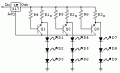
The purpose of this post is to find the most cost effective circuit for LEDs that on the one hand provide stable power for the LEDs and at the same time, if a component (LED) were to fail, the circuit automatically shuts down that part, so as to save the rest of the LEDs.


Now, I've been doing some googlesearching and came up with the following circuit http://www.onsemi.com/pub/Collateral/AND8109-D.PDF, which has already been mentioned in this thread but did not get enough attention according to me. http://forum.allaboutcircuits.com/showthread.php?p=114830
 

Attachments

Last edited:

Thread Starter

toughspeaker

Joined Jan 28, 2009
40
The above circuit (Figure 4) (thumbnail) already does fulfill the goals of this thread, but what I would like to know is, exactly in detail, how the MPS2222 work/in which direction do all the currents go when everything is nice and dandy (and shiny).

We already can read in the paper that the LM317L wants to keep the voltage of 1.25 between its Vout and Vadj, but how exactly is that happening when the MPS2222 gets involved? What voltage does the MPS2222 want between its Vout and Vadj? In addition, is there an alternative to the MPS2222/PN2222 which would do the job of that transistor better? Would it be a good idea (costefficient) to replace the LM317L with a LM2940CT-X (X=5, 12, 15)?

Would very much appriciate any help i could get.

(I'm actually going to buy these exact components to just test it out)
 

Wendy

Joined Mar 24, 2008
23,429
I'm having a slight trouble seeing it. I'm going to redraw to see if it can't be clearer.

Transistors make dandy constant current sources all by themselves though, similar to what I showed in my article. There I used diodes as the reference, with the design you showed the LM317 is the reference.
 

Thread Starter

toughspeaker

Joined Jan 28, 2009
40
Ok, let me pin down my question a bit more. Looking at the above thumbnail circuit (click on it to see a bigger pic), this is the attached text, that tries to explain what happens.

"When the circuit operates properly and all the LEDs are
running, the three sense resistors have about 1.25 V across
them, which turns the transistor switches ‘on’."

So far so good, i presume the author means the MPS2222s when he talks about "transistor switches".

"This connects all three sense resistors back to the Vadj pin allowing the
proper current to go through each leg."

Here is where I don't understand....the three sense resistors are in no way directly connected to Vadj, how can "proper current go through each leg"? Do you understand what he means Bill?
 

Wendy

Joined Mar 24, 2008
23,429
OK, figured it out. The transistor is a switch, and doesn't operate in the linear region. When it is on (current is flowing through Rs) the Collector is connected to the emitter, the circuit is a standard LM317 in current regulation mode. If an LED opens up no current flows through it, causing no voltage to be dropped across Rs. This turns the transistor off, removing the Rs from the circuit.

Each Rs sets the LM317 for 10ma (an arbitrary figure). Put 2 Rs in parallel the current doubles, 3 Rs and it triples. It is the parallel totals that increase the currents. Rs also serves another function, it allows the currents to split, helping to average the current paths. Each leg can still have minor variations in total Vf, there may be some intensity brightness variations, but it can't run away, since the transistor will cut it out of the circuit if something bad happens.

**************

I read your questions after I pressed save on the above reply. Need to catch up. :)

The only thing I don't like is the 3V drop for the LM317 is still present. This presents a problem, but it is better than a voltage regulator with separate current limiting resistors.
 

Thread Starter

toughspeaker

Joined Jan 28, 2009
40
Thank you for the clarification Bill, very nice of you! So now, we can move on. Someone on the net suggested that it might be a good idea to replace the LM317L with a LM2940CT-X (X=5, 12, 15), my question is, is there another more costeffective alternative to the LM2940CT-12? If one were to use a 24 V/8A powersource, can one just replace the LM317L directly with 2 LM2940CT-12s in parallell without anything inbetween the Vins of the transistors and the powersource?
 

Wendy

Joined Mar 24, 2008
23,429
Not so fast! I just finished redrawing the circuit. It helps sometimes.


The other regulator you suggested sounds like a 12V regulator, which leaves this behind. Have a link to the datasheet? The above schematic depends on the fact that the LM317 is adjustable. If you leave that behind then your back to a low insertion voltage regulator and some low value resistors. Is this what you want?


Looking at it, the parts count favor the voltage regulator with no real diminishment to reliability.
 

Attachments

Last edited:

SgtWookie

Joined Jul 17, 2007
22,230
There are a few caveats with that Onsemi application note;
1) Unless all of the LEDs have close Vf's, the intensity of the LED strings will vary significantly; IE: you can't mix different LED types or Vf's using one regulator.
2) You have an absolute minimum 3v dropout.
3) If an LED in a string shorted, that string would receive maximum current [see 1), above]
4) There are no advantages over using the application note suggested circuit vs using the LM317 as a normal regulator with individual current limiting resistors in the strings, but there are additional components and complexity that a standard voltage regulator circuit does not require.
 

Thread Starter

toughspeaker

Joined Jan 28, 2009
40
Not so fast! I just finished redrawing the circuit. It helps sometimes.
Thanks Bill!


The other regulator you suggested sounds like a 12V regulator, which leaves this behind. Have a link to the datasheet?
Datasheet LM2940CT-X (X=5,12,15V)
http://www.digchip.com/datasheets/download_datasheet.php?id=512362&part-number=LM2940CT-12


The above schematic depends on the fact that the LM317 is adjustable. If you leave that behind then your back to a low insertion voltage regulator and some low value resistors. Is this what you want?


Maybe your voltage regulator circuit is as good as the above "I" suggested with a LM2940CT-X. The thing is, i want to have an absolutely superefficient low-loss circuit. To my untrained eyes, it SEEMS to me that if one LED were to go in yoru voltage regulator circuit, all the other LEDs in that row would follow. Do you know how much heat your resistances dissipate? If you have time and lust, could you perhaps step by step -like the above author- guide me through each of your circuits, how the currents flow and why you chose the components you chose?
 
Last edited:

SgtWookie

Joined Jul 17, 2007
22,230
If you're stepping 24v down to 12v using a linear regulator, you're going to be throwing away more than half the power in the way of heat.
 

Wendy

Joined Mar 24, 2008
23,429
Actually the LM2940 looks like pretty good way to go. It's worst case insertion drop is 1V, my design is around 0.7V.

Designing is pretty simple actually. You figure out where the worst cases are, and design around them. With a car it is 12.0V, if the voltage drops below that the vehicle has other problems.

The other end is the Vf of the LEDs, you want to get them as close to the power supply as you can, without sacrificing performance. With the LM2940 you can go as low as 11.0V (I'm assuming worst case of 1.0V insertion drop, if I read the data sheet correctly). The space between these voltages is where the resistors go.

You can use buck boost convertors for maximum efficiency, but the problem is you can way overcomplicate a design where a simple resistor would suffice. If you have to do something like that you'd better be sure, we are talking a lot of work compared to a 2¢ resistor (literally, that is my cost).

Like Wookie said, do pay attention to the big values. Dumping 12 Volts for with a buck boost may be just the ticket, you have to use your judgement.
 

Thread Starter

toughspeaker

Joined Jan 28, 2009
40
If you're stepping 24v down to 12v using a linear regulator, you're going to be throwing away more than half the power in the way of heat.
Can't one just hook up the original circuit x 2 (the one with the highly efficient LM2940CT-12 instead of the LM317L and the MPS2222 or PN2222A for protection of the LEDs) parallelly to the +24 V source? Or am I asking an extreme noob question here which is totally obvious to everyone but me?
 

Wendy

Joined Mar 24, 2008
23,429
The LM317 is basically a 1.25 voltage regulator. It is pretty unique, but very useful. You are comparing apples to oranges, the 12V regulator wasn't designed to be part of a variable system, and doesn't make a useful constant current source (which a LM317 does). The thing is, the LM317 is also cheap, which is the other part of it.

The LM2940 (I do need to learn that number) is equivalent to the LM78XX series.
 

Thread Starter

toughspeaker

Joined Jan 28, 2009
40
The LM317 is basically a 1.25 voltage regulator. It is pretty unique, but very useful. You are comparing apples to oranges, the 12V regulator wasn't designed to be part of a variable system, and doesn't make a useful constant current source (which a LM317 does). The thing is, the LM317 is also cheap, which is the other part of it.

The LM2940 (I do need to learn that number) is equivalent to the LM78XX series.
I understand...Do you mind telling me how the LM317 will fare when it's parallelly connected to another LM317 on a 24V powersource?
 

Wendy

Joined Mar 24, 2008
23,429
You don't, why would you want to? It handles 1A just fine, and will drop 24V to 12V just fine (getting very hot in the process) if it is running at 1A.

Start with what you're doing with the LEDs, and what your power source is, then work from there. The what ifs will spin off from the setup.
 

Thread Starter

toughspeaker

Joined Jan 28, 2009
40
Thanks alot for your time Bill and Sgt Wookie, very nice of you for the tips and tricks! Ill give this a try and report back in 2 weeks time!
 

Thread Starter

toughspeaker

Joined Jan 28, 2009
40
I've got a blackout, would you mind helping me out? If we were to have an input of 12V at the Vin of the LM317, and we expect a dropdown (=loss from the LM317) of 2V, we are left at 10V. Now, for LEDs rated 20mA, what R values do I have to choose for Rsense1 and R4 assuming only ONE single LED string?

10V/20mA = ?

This cant be it, can it?
 

SgtWookie

Joined Jul 17, 2007
22,230
Why don't we step back for a moment, and explore how you're planning on powering this circuit to begin with.

You've mentioned a 24v supply.

Is this 24v coming from a regulated power supply, or is it in a vehicle such as a fire truck or some kind of military vehicle?

A regulated power supply should be quite stable. A vehicle's electrical system's voltage can vary a good bit.
 

Thread Starter

toughspeaker

Joined Jan 28, 2009
40
Sgt Wookie, thanks for helping out.

It's a 24 V 3A power supply that is stabilized. But I'm going to use as soon as I'm ready to scale up. I'll start "experimenting" with my 12 V powersupply (stabilized and can deliver up to 3 A)

(By the way, all the stuff are ordered and are ready to be assebled, but I need to make fully sure that I don't blow any part because of bad theory)
 
Top