 Facebook
 Google
 GitHub
 Linkedin
Hi,
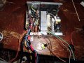
I wanted to check something before soldering. You can see where I soldered the 10W resistor between the 5V red and 0V black. This sits nicely behind the heat sink, suspended by the wires. For the connector ends, I want to use ring terminals but have to find some. Any safe/cheap way to tie these all together in some fashion that facilitates good connections?
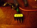
On the right are grey, green, black, and orange. The green and black connect to the power and ground of the LED toggle switch? The orange and the grey should be connected in order to allow the unit to run properly. Could the orange/grey be connected to the center terminal of the switch?
Thnx in advance
I wanted to check something before soldering. You can see where I soldered the 10W resistor between the 5V red and 0V black. This sits nicely behind the heat sink, suspended by the wires. For the connector ends, I want to use ring terminals but have to find some. Any safe/cheap way to tie these all together in some fashion that facilitates good connections?
On the right are grey, green, black, and orange. The green and black connect to the power and ground of the LED toggle switch? The orange and the grey should be connected in order to allow the unit to run properly. Could the orange/grey be connected to the center terminal of the switch?
Thnx in advance
Attachments
-
 148.7 KB Views: 47
 -
 147 KB Views: 40
 -
 148.7 KB Views: 34


