LEDs and Photoresistor

Thread Starter

RobW

Joined Nov 16, 2008
12
So I revised my project so that it no longer includes confusing EL wire circuiting, but now I need help in a different area.

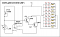
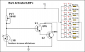
I am wiring 10+ LEDs in parallel, all with 3.3v drop and 20mA current, to a circuit that is to be controlled by a photoresistor. The input is 9v. Now, the smallest resistance range photoresistor I can find is 16k-1M ohm, but I'm only going to need between 150 and 330 ohms of resistance for the LEDs. What can I use to bring the amps back up or decrease the resistance of the photoresistor so that my LEDs aren't barely lit?

I'm a noob at this, so thanks!
-RobW
 

iONic

Joined Nov 16, 2007
1,662
The 9V you are using, is this a transformer, wall adapter...? What id the current output of the adapter? It will need to be at least 200mA as 10LED X 20ma each is 200mA.

Try this resistance calculator out... Rrsistance Calculator
 

Thread Starter

RobW

Joined Nov 16, 2008
12
Thanks for your help. I'll try to draw a diagram once I have the exact values for the components (I'll still need help figuring out how to wire the transistor and photoresistor). The power source I plan on using is a 9v DC wall adapter with 1500mA output, so I think I'm safe there.
 

Thread Starter

RobW

Joined Nov 16, 2008
12

So if I buy a PNP Transistor with 350 mW dissipation, what range of photoresistor should I look for, how should I wire it, and how will it affect the rest of the circuit?
 

Audioguru

Joined Dec 20, 2007
11,248
A transistor will saturate with a collector to emitter voltage of about 0.6V if it has enough base current when its load is only 240mA. Then it dissipates 0.6V x 240mA= 144mW. Its base current should be the load current divided by 10.
 

mik3

Joined Feb 4, 2008
4,843
Audioguru,

I am just curious if a small 200mW transistor can pass through its base 24mA (240mA/10) without being destroyed?
 

Thread Starter

RobW

Joined Nov 16, 2008
12
The only readily available photoresistors I have are unlabeled, so I'm going to have to measure the resistance or test them out. I just need to know how to wire the photoresistor and transistor into the diagram I posted above (and any other resistors needed). Thanks for your informative replies, mik3, but the photoresistor diagram on that page uses an IC chip instead of a transistor.
 

iONic

Joined Nov 16, 2007
1,662
Since I don't know if you want the LED's to light with increasing darkness or increasing lightness I'll give you one that does both!
 

Attachments

Last edited:

Thread Starter

RobW

Joined Nov 16, 2008
12
Since I don't know if you want the LED's to light with increasing darkness or increasing lightness I'll give you one that does both!
Awesome, thanks a million.
I want the LEDs to increase in brightness when the photoresistor is hit with more light (light activated, I guess).

I'm assuming the potentiometer and LDR int he diagram are representative of 1 photoresistor? So then I just need to figure out the resistance range of the photoresistor and adjust my LED resistors accordingly?

Also, would one lead of the photoresistor be connected to the base of one NPN, and the other lead connected to the negative lead of the power source? I understand how to wire the LEDs, resistors, and transistors, just not the photoresistor.

Thanks again for everyone's help so far. Sorry I'm so newb at this.
 

mik3

Joined Feb 4, 2008
4,843
If you want the brightness of the leds to vary with light intensity its better to build a simple current source with a transistor and few resistors. By varying the voltage on the base you adjust the current flowing in the collector and thus the leds current. Take care not to exceed the leds maximum current rating.
 

Thread Starter

RobW

Joined Nov 16, 2008
12
Also, just thought...

Would it not work to just find the resistance range of the photoresistor and wire the LEDs and resistors so that when the photocell is at minimum resistance, the LEDs are at normal operating mA? That way when brighter light increases the resistance of the photoresistor, the LEDs recieve less mA, thus dimming? Would I even need a transistor in this case?

(I know this would be more of a dark-activated LED system, but I think I could BS my design intention enough to justify it if its easier to pull off than a light-activated system.)
 

mik3

Joined Feb 4, 2008
4,843
No, you cant do this because the photoresistor's resistance does not drop too low to be able to light the leds and because it cant dissipate the power the leds need to work. You need a transistor.
 

Audioguru

Joined Dec 20, 2007
11,248
Audioguru,

I am just curious if a small 200mW transistor can pass through its base 24mA (240mA/10) without being destroyed?
I have never seen a 200mW transistor.
A little 2N4401 and BC337 are 625mW ones. They have a max collector current of 500mA and the saturation voltage is tested with a base current of 50mA.
 

Thread Starter

RobW

Joined Nov 16, 2008
12


Would this work correctly?

Power

LEDs
Transistors
Photoresistors (yeah, I know Radio Shack sucks bad, but its the only place I can go to get what I need before the deadline. My guess is that the values are something like these.)

I figure what I'll do is buy everything but the resistors and wire everything up except the parallel LED grid and check the amperage range across the gap where it would go, and then buy a value of resistor that keeps them running at 30mA max.
 

iONic

Joined Nov 16, 2007
1,662
Are you sure that the LED's are rated for sustained 30mA. Generall the nominal current is 20mA and "absolute Max" of 30mA. Running them at 30mA continuously might not fair well for the life of the LED's.

The new circuit you provided not not appear, in my opinion to be operable.
 

Thread Starter

RobW

Joined Nov 16, 2008
12
If you click the LED link, it gives you the spec sheet. They're blue LEDs, so they run at a higher power than other LEDs. It lists max(peak forward current) at 50mA and norm(continuous forward current) at 30mA.

The new circuit you provided not not appear, in my opinion to be operable.
How might I fix this?
 
Top