Identify IC to mod sony alarm clock to 12H mode

Status
Not open for further replies.

Thread Starter

lelo

Joined Aug 23, 2008
3
hi guys,

i have a small mod project.

i plan to mod a sony alarm clock (dream machine): ICF-C318 which only have 24H mode to 12H mode.

i have done this to previous model which use IC sanyo LM8560.

but this time, i'm facing a problem to identify the clock IC of ICF-C318.

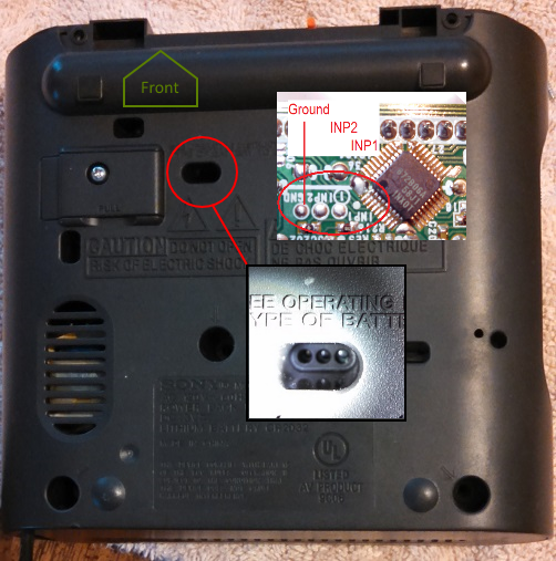
it have 36-pin. the wordings at IC is:
872B06
58J
8PX0

i believe this IC supports radio wave clock syncronizing.

i've searched the web with no result.

i attached the picture here, could anyone help to identify this IC?

Or who have ICF-C318S (C318/S) model to share its circuit.

regards
 

Attachments

Last edited:

Thread Starter

lelo

Joined Aug 23, 2008
3
hi guys,

from my study on the circuit, and assumed that the 12H/24H selection is by supplying the pin with voltage or open, i filtered it to pin#5, #9, #14 and #17.

but i'm poor at soldering.
could anyone suggest a method to tap the trace with a jumper cable thingy and disconnect the voltage?

thanx
 

Thread Starter

lelo

Joined Aug 23, 2008
3
You can try lifting the legs of the IC, may be better than cutting traces.
hi,

thanx for the reply.
i really dont want to de-solder and mess with the IC.

do u think, by applying a reverse voltage, i.e. -4V can cancel out the voltage of 4V??

regards
 

thesavo

Joined Aug 28, 2013
5
I have a Sony dream machine icf-c218. I'm in the USA and want the opposite. I want it to show in 24-hour mode, not 12-hour. It looks like we could benefit from each other.
I now this thread is ancient history by now.
 

thesavo

Joined Aug 28, 2013
5
*know - editing is disabled

Here is a picture of my Clock IC


It looks like a 36 pin SMD chip. The readout on mine is
872B06a
58J1
1NX0T

from my study on the circuit, and assumed that the 12H/24H selection is by supplying the pin with voltage or open, I filtered it to pin#5, #9, #14 and #17.
I would have annotated my own picture but I can't tell which corner is pin one.
 

thesavo

Joined Aug 28, 2013
5
Does yours have 3 solder pads on the bottom of the logic board? MY ICF-C218 (US) does. I wonder if it is some sort of Serial I/O port? Perhaps we should look at this thing. My theory is that perhaps this is used at the factory to program it for the destination market or country.

It's next to the clock IC (assuming the other 28 pin DIP is for radio functions). Keywords we should be looking for are: IC101, INP 1, INP2


http://i1344.photobucket.com/albums.../Sony_ICF-C218/Bottom-per30-2_zps034a58bb.png
 

Wendy

Joined Mar 24, 2008
23,421
A thread belongs to the OP (original poster). Trying to take over someone elses thread is called hijacking, which is not allowed at All About Circuits.

In addition, you have practiced the arcane art of necromancy, the revival of a long dead thread. Likely the OP (Original Poster) has solved his problem in the years that has passed, or thrown it away, or something.

Start your own thread on the subject.
 
Status
Not open for further replies.
Top