
This project is licensed under a Creative Commons Attribution-ShareAlike license (essentially, it's free to use for any purpose, but any modification must also be shared the same way). See the footer for details.

This Lab PSU is based on the one displayed in the LM317 datasheet, named "5A Constant Voltage/Constant Current Regulator", shown here for reference:

As you can see from the version in the datasheet, -6v are needed to allow the opamp to pull down the output of the LM317 to 0v in case of a short-circuit scenario, so i decided to use a 15+15vac 3A transformer (in fact, i already had it, it should be possible to go to 20+20vac, using a beefier heatsink), and built also a negative version of the circuit, so that it can be used to test amplifiers and other circuits requiring a split supply. The transformer must have 3A, as they lose efficiency when not supplying a resistive load, and a rectifier w/capacitive filter has nothing of resistive. It's recommended to not exceed the Amp rating divided by 1.8 for this kind of load.
I kept the voltage and current at reasonable levels. 35v and 5A as seen in the datasheet are simply not possible, as they would kill the LM301A (36v absolute maximum supply voltage, but 41v applied here). The LM101A or LM201A would withstand it, however. Anyways, no single transistor will survive 35v x 5A = 175 watts of power disipation, so there's no way unless you want to use several power transistors and a huge heatsink. When needing so much current, a variable linear design is not the best idea in the world, anyways.
I also changed the transistors for newer versions, modified the voltage regulation area to go near 0v, and moved the 1uF capacitors closer to the input of the LM3x7 to avoid some unstability problems that i detected when working in constant current mode. I used the TO-220 version of the regulators, i see no point on using TO-3 regulators, like suggested on the original circuit.
I also named the project "Open Lab PSU", and put it under a Creative Commons license (details in the footer).
The PSU consists of 3 small boards: the rectifier board, and the positive and negative boards.
The rectifier board
The rectifier board has the rectifier, capacitor bank, and +6v and -6v regulators.

The positive board
The positive board has the positive regulator and current limit circuit.

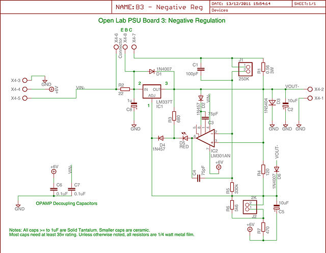
The negative board
The negative board has the negative regulator and current limit circuit.
Issues
To the date, the only issue i detected, is that the positive board has ripple in a very definded "grey area" between CV and CC mode. For example, the following image shows the worst case detected of 53 mv peak-to-peak ripple when the PSU is configured to limit on 12v 0,8A over a 15Ω resistor (just on the verge of current limit):

Raising or lowering the current limit by 20mA out of that zone gives the following readings:

Build details
I mounted both power transistors with mica insulators and thermal compound to the same ZD-2K heatsink, it has a thermal resistance of 0.92 °C/W. If you use a bigger transformer, you need to recalculate the heatsink for safe worst-case scenario operation. Also modify R6, the 2k potentiometer and/or R1 for a different voltage/current limit.
I put 6225D heatsinks on the LM3x7 regulators. They have a 10°C/W thermal resistance, but they're overkill, you can use 20°C/W.
About the fuses for the mains side, it varies by country. I have 220v here, so i used a 1A fuse (90VA transformer rating / 220v ~= 0.4A). All fuses must be of slow-blow type, because the inrush current is high.
I still didn't decide where to put the fuses on the low-voltage side. Putting them before the rectifier board seems to be the safest, but the capacitors will charge at great currents on turn-on, so slow-blow fuses shoud be used. Normal operation is up to 1.67A, so the fuses must probably be the next bigger value. Not tested, however.
Another thing to note, is that the red leds aren't soldered into the board directly, they go in the front panel. I soldered polarized "power" connectors there, but decided to keep the led in the schematic, because it shows correct polarization, and the pinout matches.
The current limit circuit is a high impendance input. I kept wires short and used twisted cable to avoid noise pickup.
The project is available in Cadsoft Eagle 5.11 format, attached in this blog entry.
Open LAB PSU by Fernando Rapetti is licensed under a Creative Commons Attribution-ShareAlike license. For attibution, a link to this page (http://forum.allaboutcircuits.com/blog.php?b=480) must be included on any derivative work. Note that you build this at your own risk, i would not be held responsible for any damage.