
Two stage BJT amplifier with feedback
- Thread starter The Electrician
- Start date
Scroll to continue with content
Why should there be any oscillations? If RFB is > 1673.424 ohms, then the negative feedback is greater than the positive feedback.The pspice shows the oscillations already for RFb=2344.06792623
I don't see any oscillations in spice and tnk didn't mention any occurring if RFB is greater than 1673.424+ ohms.
Make sure the transistor beta is set to the correct value in your simulation.
For those values, the critical resistance would be 1645.1766Ω. For RFB greater than that, there shouldn't be any oscillations. I would think that if RFB > 1800Ω, there definitely shouldn't be any oscillations.Well the beta are 192, 187. This make any difference?
Sorry I haven't chimed in on this one. I've been busy lately, but I'm watching this thread with interest and would like to see your solution with the generalized admittance matrix.... I hope we'll hear from hgmjr and steveb.
Just to contribute something without spending too much time, I thought I would mention the method of inspection for the input impedance calculation. It is not too difficult to write the input impedance formula just by looking and noting the effective reflected impedances caused by the current gains.
By inspection I get the following input impedance formula, where the // symbol means parallel combination.
\( R_i_n=R_1//R_2//\Biggl(\biggl(h_f_e_1+1\biggr)\biggl(r_e_1+r_e_1_1// \bigl(R_f_b+r_e_1_2// (r_e_2+{{R_3//R_4//R_c_1}\over{h_f_e_2+1}})\bigr)\biggr)\Biggr)\)
For the first circuit with infinite feedback resistor, I get Rin=11272 ohms and for the second circuit with 2344 ohm feedback resistor, i get Rin=11180 ohms.
Hopefully, I didn't make a mistake.
Apparently a mistake has crept in there somewhere, because with the feedback resistor, the input impedance is 5506.429Ω. :-(For the first circuit with infinite feedback resistor, I get Rin=11272 ohms and for the second circuit with 2344 ohm feedback resistor, i get Rin=11180 ohms.
Hopefully, I didn't make a mistake.
With Rfb = 5000 plugged into my EXCEL spreadsheet version ....
I get Gain= 6.9244614202E+02
And using goal seek in the spreadsheet I get Rfb = 1.6734242404E+03
to achieve a gain of 1E+12 (not infinity but getting there!). Actually Goal Seek falls over with a target >> 1E+12 ....
Haven't even thought about the black box challenge.
I get Gain= 6.9244614202E+02
And using goal seek in the spreadsheet I get Rfb = 1.6734242404E+03
to achieve a gain of 1E+12 (not infinity but getting there!). Actually Goal Seek falls over with a target >> 1E+12 ....
Haven't even thought about the black box challenge.
I also get this value in my spreadsheet calculation.Apparently a mistake has crept in there somewhere, because with the feedback resistor, the input impedance is 5506.429Ω. :-(
Some small error must have crept in; the gain should be 689.001136. Jony130 went back and edited post #17 and got the results for the RFB = 5000Ω case.With Rfb = 5000 plugged into my EXCEL spreadsheet version ....
I get Gain= 6.9244614202E+02
Are you using the nodal method? In post #15 you got the original gain as about 1645, which is pretty close to the exact value of 1646.5301225. You were going to recheck that value. What do you get for it now? Are you still a little off? Maybe a small error in your spreadsheet.
That's correct.And using goal seek in the spreadsheet I get Rfb = 1.6734242404E+03
to achieve a gain of 1E+12 (not infinity but getting there!). Actually Goal Seek falls over with a target >> 1E+12 ....
All correct except for some numeric errors beginning to creep into your results around the 6th decimal place.For RFB=5K
If I don't make any mistake in calculation here are the result:
V1=0.578180V---> node 2 in your diagram
V2=-46.318011V--->it is a Ku= node_3/node_1 in your diagram
V3=-38.341042V--->Ku=node_4/node_1 in your diagram
and
Ku=node_5/node_1|=((V2-V3)/R7) *β2 *R6=689.000225[V/V]
Rin=R2/(1-V1)=18481.5798Ω ---> not take into account R1,R2 in your schematics.
And gosh I need a spreadsheet. [/URL]
Referring back to your post #13, I said:
Do you have any ideas on this one?You have in effect analyzed a circuit that has an AC ground connected to node 2 and and with RFB connected from node 4 to ground, rather than between nodes 2 and 4. Such a circuit has exactly the same gains from node 1 to all the other nodes.
Now, to extend the problem, imagine this. Build each circuit, my original one and the one you analyzed and enclose each one in a black box. Each circuit's reference node (ground) is connected to the metal of the box. The other 5 nodes are connected to terminals on the outside of the box. Since both circuits have exactly the same gains from node 1 to the other nodes, how can we tell them apart?
Exactly correct. Did you find the cause for the small error in gain you had in post #27?With Rfb=5000, I get Rin = 9.307408213914E+03
That's it for me - thanks for the challenge Electrician, but it's worn me out!
Thanks Electrician - I found the error in my spreadsheet and it all now agrees with the values you and Jony130 have found for the various values of Rfb.Some small error must have crept in; the gain should be 689.001136. Jony130 went back and edited post #17 and got the results for the RFB = 5000Ω case.
Interesting! It seems that the feedback modifies the effective current gains, which makes it more difficult to see the input impedance by inspection. This proves your initial point ....Apparently a mistake has crept in there somewhere, because with the feedback resistor, the input impedance is 5506.429Ω. :-(
I'll look at it some more to see if a more "intelligent" inspection can yield the correct answer, or if a full calculation is necessary.I want to show how just the addition of a single feedback resistor, RFB, between the two emitters substantially increases the difficulty of analysis.
EDIT: I don't see an easy way to get the input impedance by inspection. The effective current gain in each stage seems highly dependent on the interaction between stages. At this point I would just use "brute force" and write out the equations, which might take me about an hour to do without mistakes. However, I just don't have the time now. I'm curious to see how the admittance matrix approach simplifies the calculation.
Last edited:
Ah, this is interesting. I just noticed that this input impedance is what you expect if the emitter resistor of stage 1 was completely bypassed. So basically, your feedback resistor is negating the effect of the unbypassed portion of the emitter resistor on stage 1. For the AC signal, the emitter of the stage 1 transistor acts like a virtual ground. Correct?the input impedance is 5506.429Ω. :-(
Yes, I chose the value of RFB to get just that effect. Jony130 noticed it in post #13.Ah, this is interesting. I just noticed that this input impedance is what you expect if the emitter resistor of stage 1 was completely bypassed. So basically, your feedback resistor is negating the effect of the unbypassed portion of the emitter resistor on stage 1. For the AC signal, the emitter of the stage 1 transistor acts like a virtual ground. Correct?
But, which circuit have the same gains ?Now, to extend the problem, imagine this. Build each circuit, my original one and the one you analyzed and enclose each one in a black box. Each circuit's reference node (ground) is connected to the metal of the box. The other 5 nodes are connected to terminals on the outside of the box. Since both circuits have exactly the same gains from node 1 to the other nodes, how can we tell them apart?
For sure not those in the first post.
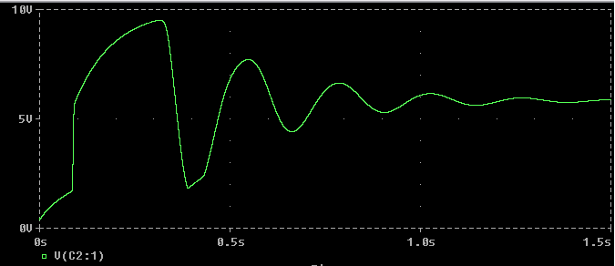
And pspice show oscillation for RFB=2.5K, CFB=100uF and β1=300; β2=200.
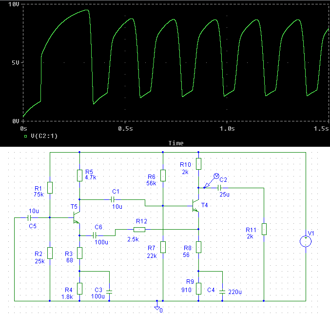
And for RFB>3K oscillations disappear
When I said in post #18:But, which circuit have the same gains ?
For sure not those in the first post. [/URL]
I was referring to your analysis in post #13, and the second of my original circuits, the one with RFB present.You have in effect analyzed a circuit that has an AC ground connected to node 2 and and with RFB connected from node 4 to ground, rather than between nodes 2 and 4. Such a circuit has exactly the same gains from node 1 to all the other nodes.
Now, to extend the problem, imagine this. Build each circuit, my original one and the one you analyzed and enclose each one in a black box. Each circuit's reference node (ground) is connected to the metal of the box. The other 5 nodes are connected to terminals on the outside of the box. Since both circuits have exactly the same gains from node 1 to the other nodes, how can we tell them apart?
That's very interesting. If I make RFB 2500, I get very low frequency oscillations after a second or so.And pspice show oscillation for RFB=2.5K, CFB=100uF and β1=300; β2=200.
And for RFB>3K oscillations disappear

If I make C6 = 10uF, the oscillations don't start.
If I make C1 = 1uF (and restore C6 to 100uF), the oscillations don't start.
A full analysis of the circuit, including the effect of all the capacitors (which we haven't included so far in this thread), should show why this happens.
You May Also Like
-

Silicon Labs and Arduino Team Up to Democratize Matter
by Jake Hertz
-

Keysight Introduces First Integrated Toolset for Quantum System Design
by Duane Benson
-

Microchip Eases USB Integration With New 8-bit MCU Family
by Duane Benson
-

VISC: The New Coprocessing RISC-V Architecture for AI Efficiency
by Duane Benson