
Oh, you want linear with that. New circuit for you to try:
Attachments
-
2.4 KB Views: 30
You can't go all the way to the rails, but if a range of ~18mV to ~14.99V would do, a 555 is an easy way to make a reasonably nice saw tooth waveform.My mainly needs is to find a schematic that would me assure an excursion of the triangle wave between 0 and 15 volt, and would be nice if I can adjust this waveform between 200 and 1200 hz.

Symmetry?Hello,
Take the 555 oscillator with a rail-to-rail output op-amp and amplify it 3 times.
Bertus
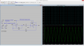
Apart from the slight delay at top and bottom, it's quite fine, as long as you don't hit it with a serious real world load (like 500 Ohm). and that describes very well, why I advocate a bit more supply voltage, than what the output should be.Below is the LTspice simulation of a dual rail-rail op amp circuit that will generate close to a 0V to 15V adjustable frequency, linear triangle-wave from a single 15V supply.
Arrrgh, I somehow got the impression that a saw tooth was asked for and the family calls for (and deservesIt uses no 555 which is not well suited to generating a linear triangle wave.
") ) my attention, holiday considered, but perhaps I'll change it at a later time.
) my attention, holiday considered, but perhaps I'll change it at a later time.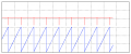
Depends upon your definition of A-OK......................
Blue trace is 5V/div, generated with a LM555N. Just like with your circuit, it gets a teeny bit ugly near the rails, but apart from that, linearity is A-OK!

Unless you add circuitry to linearize it, the sawtooth from a 555 is actually part of an RC charging exponential curve.And your definition likewiseDepends upon your definition of A-OK.
Does that exclude other components in your book?[...] the 555 is a actually a very clever little oldie, especially when you have the imagination to really use it
"Look" is not how you determine linearity. You determine linearity by measurements along the waveform and calculating the deviation from an ideal straight line. How linear an RC charging waveform looks depends upon the display settings and the portion of the curve you have displayed....................
Does it look exponential to you???
Does it look less linear than your circuit to you???
When did I ever say I didn't add circuitry?
You didn't and I didn't say you didn't.
........................
Does that exclude other components in your book?
Of course not. I didn't say that either. I was just trying to determine if you added extra circuitry to make the waveform more linear (such as adding a constant-current source to charge the timing capacitor).
.....................
Or start with 20Vdc supply to make 15V.Does the triangle wave really need to go as high as 15V? You would have a wider choice of components if you could manage with, say, 10V.
I've never mentioned RC charging and even a blind man can see that the waveform that I posted is CC charging, so I'll write off your repeated mentioning of RC charging as a slightly antagonistic way of being "right" (as I'm sure you know better)."Look" is not how you determine linearity. You determine linearity by measurements along the waveform and calculating the deviation from an ideal straight line. How linear an RC charging waveform looks depends upon the display settings and the portion of the curve you have displayed.
My other answers are above in blue.
and while I can't speak for others, personally, I have no trouble eyeballing whether a waveform is, for the purpose of non-extremely-critical uses, to be considered linear enough.All I wanted to know was whether a constant current source had been added to the 555 circuit and now you have finally verified that, but only after several condescending comments from you. Eyeballing circuit design details from a waveform is not something I do (even though I'm not blind).I've never mentioned RC charging and even a blind man can see that the waveform that I posted is CC charging, so I'll write off your repeated mentioning of RC charging as a slightly antagonistic way of being "right" (as I'm sure you know better).
.................
No it is not, it is essentially the same as what Carl posted in #24, except it doesn't come close to making the 0V to 15V that the TS needs (from a 15V supply).Here's another way
What do you mean its not...IT IS a triangle generator.No it is not, it is essentially the same as what Carl posted in #24, except it doesn't come close to making the 0V to 15V that the TS needs (from a 15V supply).
It is not "another way", it is not even "a way".What do you mean its not...IT IS a triangle generator.
Yes...I didn't see post #24. In concept, its the same thing.It is not "another way", it is not even "a way".
Hi,Since I see the LT1498 in the DigiKey list, so I repeated the sim with that part. Note I can increase the gain of the buffer amp a bit, and get pretty close to the rails.
View attachment 83392
Just use the positive supply for your 0V reference and it will be - don't feed your other circuitry from the same supply then.However, there is a way, adding some components to this circuit, to invert the output wave? I mean: obtain a triangular wave which can go from 0 to -15 volt.

by Aaron Carman

by Duane Benson

by Duane Benson

by Duane Benson