
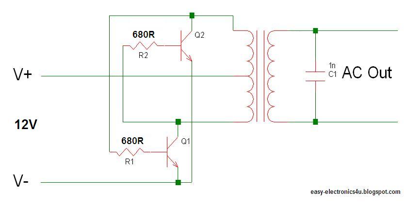
_An inverter is a circuit that converts dc voltage to ac voltage, The circuit uses two power transistors, two power resistors, and the transformer.


_The transistors determine how much power the inverter can supply, and the transformer determines the input and output voltage, also it should handle the needed power, so more power means bigger transformer, The least expensive and the easiest way to get a big transformer is to re-wind an old microwave transformer, they supply at about 1KW.
_You can choose any high power transistor, according to your needed current for exemple 2N3055 2SC5200 2N3773 MJ2955 2sd1047 2SC2922 2SA1943...
_A good 12v battery should be used to supply the wanted power, Remember, when operating at high powers, the circuit draws big amounts of current. so be careful not to let your battery go dead!!!
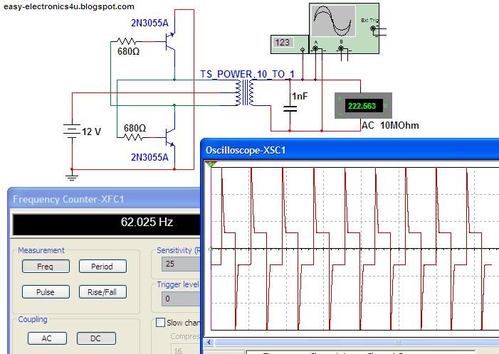
This image shows some of the caracteristics of the circuit:

http://easy-electronics4u.blogspot.com/
Thanks.
_The transistors determine how much power the inverter can supply, and the transformer determines the input and output voltage, also it should handle the needed power, so more power means bigger transformer, The least expensive and the easiest way to get a big transformer is to re-wind an old microwave transformer, they supply at about 1KW.
_You can choose any high power transistor, according to your needed current for exemple 2N3055 2SC5200 2N3773 MJ2955 2sd1047 2SC2922 2SA1943...
_A good 12v battery should be used to supply the wanted power, Remember, when operating at high powers, the circuit draws big amounts of current. so be careful not to let your battery go dead!!!
This image shows some of the caracteristics of the circuit:
http://easy-electronics4u.blogspot.com/
Thanks.


