TDA7297 not working

Thread Starter

Pho3niX90

Joined Aug 19, 2013
12
Hey guys,

I am trying to learn circuits and electronics, have read some topics online, subscribed to some youtube channels ect. and then decided I will make my first project a small amplifier for a carputer project.

I started a week ago assembling everything and found some circuits online and tried replicating it, went out to my local electronics shop and bought 3 times of everything I needed in case I make a mistake.

I am using a dedicated powersource, and tried giving the project 12v 1.5amps, but nothing is working, I am not sure what I am doing wrong, the circuit I am using is this:


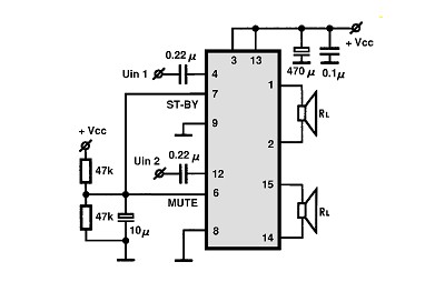
I have started from scratch about 3 times, each time using a new tda7297 just to make sure the chip isn't busted. I can't even get the faintest sound of the project,

Any advice on what I might be doing wrong? Like I said this is my first project ever.


Thanks in advance!!
 

Thread Starter

Pho3niX90

Joined Aug 19, 2013
12
Thank you so much for your fast reply, love seeing communities that are this alive.

Here are the pics of front and back, might look horrible compared to a professional or even to someone that knows what they are doing, the soldering isn't that impressive as well, will be getting my new soldering gun in a few days.

You will notice there are 2 sides, the board actually has 2 chips on to give me 4 channels, but atm I am just powering the one chip until I get it right.


Shagas

Joined May 13, 2013
804
Double check that you have everything wired up correctly and used the right components .
Check if you do infact have an input signal present .


What is your input signal voltage , are you using a phone or mp3 player?
If it's too high then the TDA (at least the ones I used) , instead of distorting into oblivion just simply don't respond , no idea why. Happened to me the first time I was trying to build an amp with a TDA chip. Try attenuating your signal using a voltage divider of 10k/1k or something similar ( google voltage divider) . Again , this is counter intuitive but try it anyway .

Also , I see pin 9 is called standby and it's connected to ground . Try unplugging it from ground and see if that helps.
 
Last edited:

Thread Starter

Pho3niX90

Joined Aug 19, 2013
12
Double check that you have everything wired up correctly and used the right components .
Check if you do infact have an input signal present .


What is your input signal voltage , are you using a phone or mp3 player?
If it's too high then the TDA (at least the ones I used) , instead of distorting into oblivion just simply don't respond , no idea why. Happened to me the first time I was trying to build an amp with a TDA chip. Try attenuating your signal using a voltage divider of 10k/1k or something similar ( google voltage divider) . Again , this is counter intuitive but try it anyway .

Also , I see pin 9 is called standby and it's connected to ground . Try unplugging it from ground and see if that helps.
Thanks.

The signal is sent from a phone (note 2) to be exact, I have tried my laptop as well to no avail.

What should the signal voltage be? I have went through everything numerous times, the weird thing though is I do have a signal, but once it goes through the 0.22μ (blue ones on the board.) then there is no signal to be found anymore??

I grounded it at that point due to the circuit I used posted in the first post, or did I understand it incorrectly?
 

tubeguy

Joined Nov 3, 2012
1,157
Pin 8 and pin 9 should be grounded.
Pin 6 is mute, and pin 7 is stand-by. These pins should measure about 1/2 of the power supply voltage. (6 volts with a 12 volt supply)

Why don't you post the voltage readings on each of the IC pins, measuring between the power supply ground and each pin. Of course, be careful not to short any pins together. :)

What speakers are you using ?
 

Thread Starter

Pho3niX90

Joined Aug 19, 2013
12
Pin 8 and pin 9 should be grounded.
Pin 6 is mute, and pin 7 is stand-by. These pins should measure about 1/2 of the power supply voltage. (6 volts with a 12 volt supply)

Why don't you post the voltage readings on each of the IC pins, measuring between the power supply ground and each pin. Of course, be careful not to short any pins together. :)

What speakers are you using ?
Thanks, will measure them and report back once I get home.

I am testing with 2 different speakers at different instances, one is a very small speaker taken from a Lilliput touchscreen, the other was a home theater speaker (10w).

Pin 6 and 7 is currently grounded and connected to vcc+
 

Thread Starter

Pho3niX90

Joined Aug 19, 2013
12
Okay guys,

Here are my readings on each pin.

1 = 12.1
2 = 12.1
3 = 12.2
4 = 12.1
5 = 0.0

6 = 12.1
7 = 12.2

8 = 12.1
9 = 12.1
10 = 0.0
11 = 12.2
12 = 12.0
13 = 12.2

14 = 12.1
15 = 12.1


Not sure how to test the source from the "player", but voltages art and [f]inish (they start and then descend to 0)
s1 = s9 f0
s2 = s0.5 f0
 

Shagas

Joined May 13, 2013
804
Yes .
Once again: have you tried varying the signal amplitude?
Putting your phone volume to lowest and going up from there ?
 

Thread Starter

Pho3niX90

Joined Aug 19, 2013
12
Yes .
Once again: have you tried varying the signal amplitude?
Putting your phone volume to lowest and going up from there ?
Thank you very much for your help thus far.

I have tried putting the phone on mute, and stepping the volume up by 1 every 10 seconds, didn't work.

I also did the voltage reading without the signal, still the same voltages.
I am not sure what I am doing wrong
 

bertus

Joined Apr 5, 2008
22,276
Hello,

It looks like there are some ground signals missing.
That's why most pins read 12.- volts.

1 = 12.1
2 = 12.1
3 = 12.2
4 = 12.1
5 = 0.0

6 = 12.1 -> should be around 6 Volts, for 12 Volts supply
7 = 12.2 -> should be around 6 Volts, for 12 Volts supply

8 = 12.1 -> should be 0 Volts, as it should be ground.
9 = 12.1 -> should be 0 Volts, as it should be ground.
10 = 0.0
11 = 12.2
12 = 12.0
13 = 12.2

14 = 12.1
15 = 12.1

Bertus
 

Thread Starter

Pho3niX90

Joined Aug 19, 2013
12
Thank you bertus,

Am I correct to say that the left portion of the schema below should be grounded and connected to the positive?


Thread Starter

Pho3niX90

Joined Aug 19, 2013
12
Also, my caps negative terminal is pointing towards the ground on the left bottom side of the circuit (in picture), is this correct?
 

Shagas

Joined May 13, 2013
804
Also, my caps negative terminal is pointing towards the ground on the left bottom side of the circuit (in picture), is this correct?
Yes that is correct.
Also the left bottom portion shows that the top is connected to VCC and the bottom to ground.

Are you sure that you connected everything according to the schematic?
I think you ignored something important that you mistakenly took for unimportant
 

Thread Starter

Pho3niX90

Joined Aug 19, 2013
12
I have gone over everything and can't see anything I missed.

The left bottom is grounded and connected to positive, the caps negative is showing towards the grounding side.

top right on circuit, the caps are connected on positive and negative, the negative side of the caps are connected to ground.

I removed the smal caps on the vcc and ground, was thinking becuase there is no polarity that it's passing the voltage over to ground, but still reading the same voltages.

I seriously don't know what I am doing wrong, is that circuit even right? I pulled it of google images
 

bertus

Joined Apr 5, 2008
22,276
Hello,

I think you have a problem with reading the schematic.
I have circled all ground connections.
These should ALL be connected to the - connection of the power supply.


Bertus
 

Attachments

Thread Starter

Pho3niX90

Joined Aug 19, 2013
12
Thanks bertus.

All those are currently connected to the ground, and also negative from power supply also connected to ground?
 

bertus

Joined Apr 5, 2008
22,276
Hello,

How is your power supply connected to the amplifier?
Does it have 2 or 3 connectors?

A picture of how every thing is connected ( including the power supply ) would be helpfull.
Normaly the - connection of the power supply is ground.
It looks like the - connections are floating, as you are measuring 12 volts on them.

Bertus
 
Top