
Hello All About Circuits,
Have been experimenting with LED displays
connecting 555 timers to 4017 decade counters
to creates sequences of running lights.
Have branched out to a larger display. This
one has about 300 LEDs.

This is an animated GIF of the effect that is sought.
This animation shows four of the eight characters
that are the complete plan.
This shows about 150 green LEDS. The project will
have a little over 300.
The set up is an Arduino Uno to a Max7219 to a
breakout board.
The Max7219 controls 64 lights and can be daisy chained
so five Max7219s are needed.
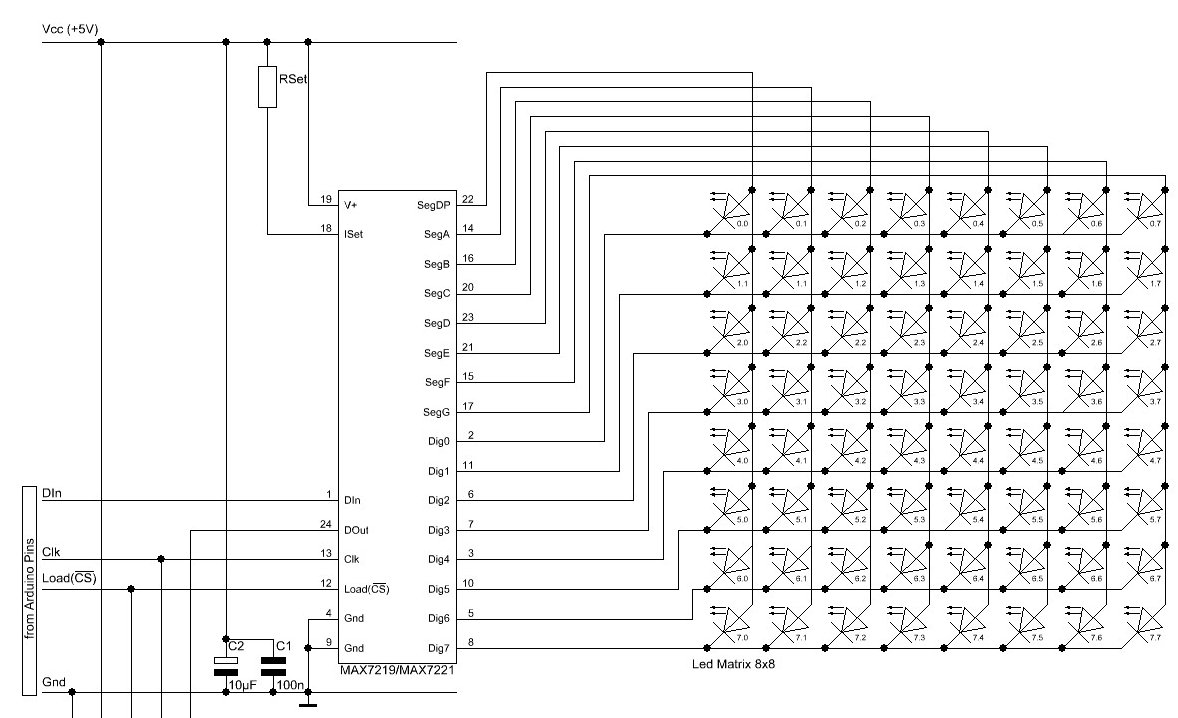
The Max7219 is actually designed to operate either an
eight-by-eight matrix or a seven segment LED.
This is the schematic of the Max7219 to an 8x8 matrix.
To translate the matrix layout into a linear layout
the schematic was redrawn. (This shows 24 of the
64 connections. 40 more would be done using
this pattern and four more boards would be daisy-chained
from the first.)

This is a pictorial of the PCB (Datak 21-117) which holds the 7219
and the PCB (Vector 8022) used to break out the matrix.

The design works well with a dozen LEDs on a bread board
but now, with over thirty connections made to LEDs set in holes
drilled in an acrylic sheet the rats nest is becoming
unworkable. An eight inch long female to female
two position Dupont jumper connector is connected to two leads
on the Vector 8022 on one end and to the LED leads at the other end.

So the question is more one of construction than electronic design.
Or perhaps the electronic design chosen is causing the
the construction nightmare.
One of the problems is the wires leads from Vector 8022
tend to get loose from the Dupont connectors. Perhaps
cutting and stripping the female to female jumpers and soldering
the stripped end to the leads coming off the Vector 8022
so the only connector would be at the LED would improve things.
The female Dupont connections at the LEDs seem to be more stable.
Conceptually some way of simplifying the connection between
the Max7219 and the LEDs is sought. Maybe another plane of
acrylic sheet with wiring to make the Vector 8022 to LED connection
less hectic.
If anyone has any ideas about to simplify the wiring I would appreciate
it greatly.
Thanks.
Allen in Dallas
Have been experimenting with LED displays
connecting 555 timers to 4017 decade counters
to creates sequences of running lights.
Have branched out to a larger display. This
one has about 300 LEDs.
This is an animated GIF of the effect that is sought.
This animation shows four of the eight characters
that are the complete plan.
This shows about 150 green LEDS. The project will
have a little over 300.
The set up is an Arduino Uno to a Max7219 to a
breakout board.
The Max7219 controls 64 lights and can be daisy chained
so five Max7219s are needed.
The Max7219 is actually designed to operate either an
eight-by-eight matrix or a seven segment LED.
This is the schematic of the Max7219 to an 8x8 matrix.
To translate the matrix layout into a linear layout
the schematic was redrawn. (This shows 24 of the
64 connections. 40 more would be done using
this pattern and four more boards would be daisy-chained
from the first.)
This is a pictorial of the PCB (Datak 21-117) which holds the 7219
and the PCB (Vector 8022) used to break out the matrix.
The design works well with a dozen LEDs on a bread board
but now, with over thirty connections made to LEDs set in holes
drilled in an acrylic sheet the rats nest is becoming
unworkable. An eight inch long female to female
two position Dupont jumper connector is connected to two leads
on the Vector 8022 on one end and to the LED leads at the other end.
So the question is more one of construction than electronic design.
Or perhaps the electronic design chosen is causing the
the construction nightmare.
One of the problems is the wires leads from Vector 8022
tend to get loose from the Dupont connectors. Perhaps
cutting and stripping the female to female jumpers and soldering
the stripped end to the leads coming off the Vector 8022
so the only connector would be at the LED would improve things.
The female Dupont connections at the LEDs seem to be more stable.
Conceptually some way of simplifying the connection between
the Max7219 and the LEDs is sought. Maybe another plane of
acrylic sheet with wiring to make the Vector 8022 to LED connection
less hectic.
If anyone has any ideas about to simplify the wiring I would appreciate
it greatly.
Thanks.
Allen in Dallas


