
Hello people.
I am designing an power inverter.
My idea is transform 12VDC in 120VAC@60Hz.
I will make a signal PWM at 25Khz comparing a triangle wave and a sine wave. OK.
But, to make things simpler in the beginning, I am testing with an static square wave at 25Khz provided by a 555 IC.
I threw this signal on a IR2184 gate driver to switch my two IRFP460 mosfets.
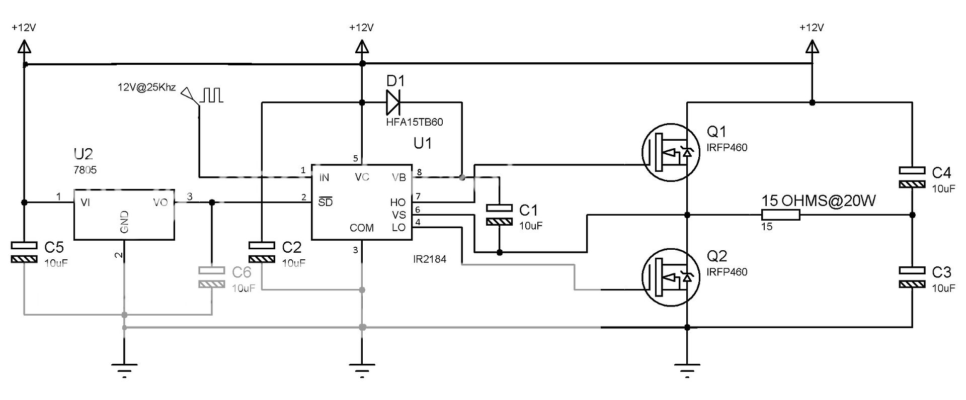
So I started with a basic circuit:

This one is working very well. I am using a single power supply with 12VDC. Look the all the power lines and grounds are the same.
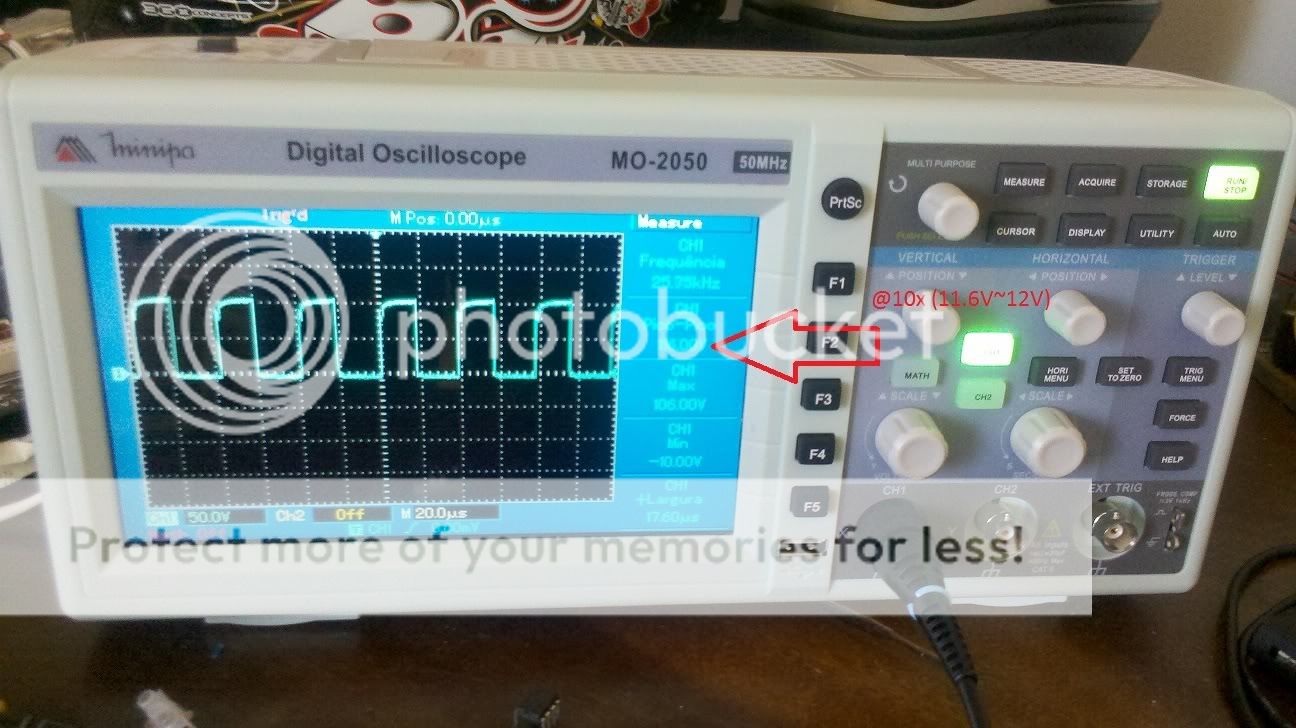
The signal at my gate is ~12V. Nice:

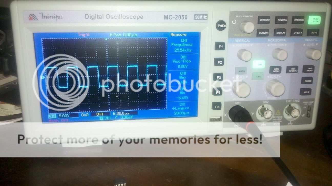
And measuring the voltage across the resistor I came with this:

12Vp.p. It looks that is working.
 .
.
BUT.....
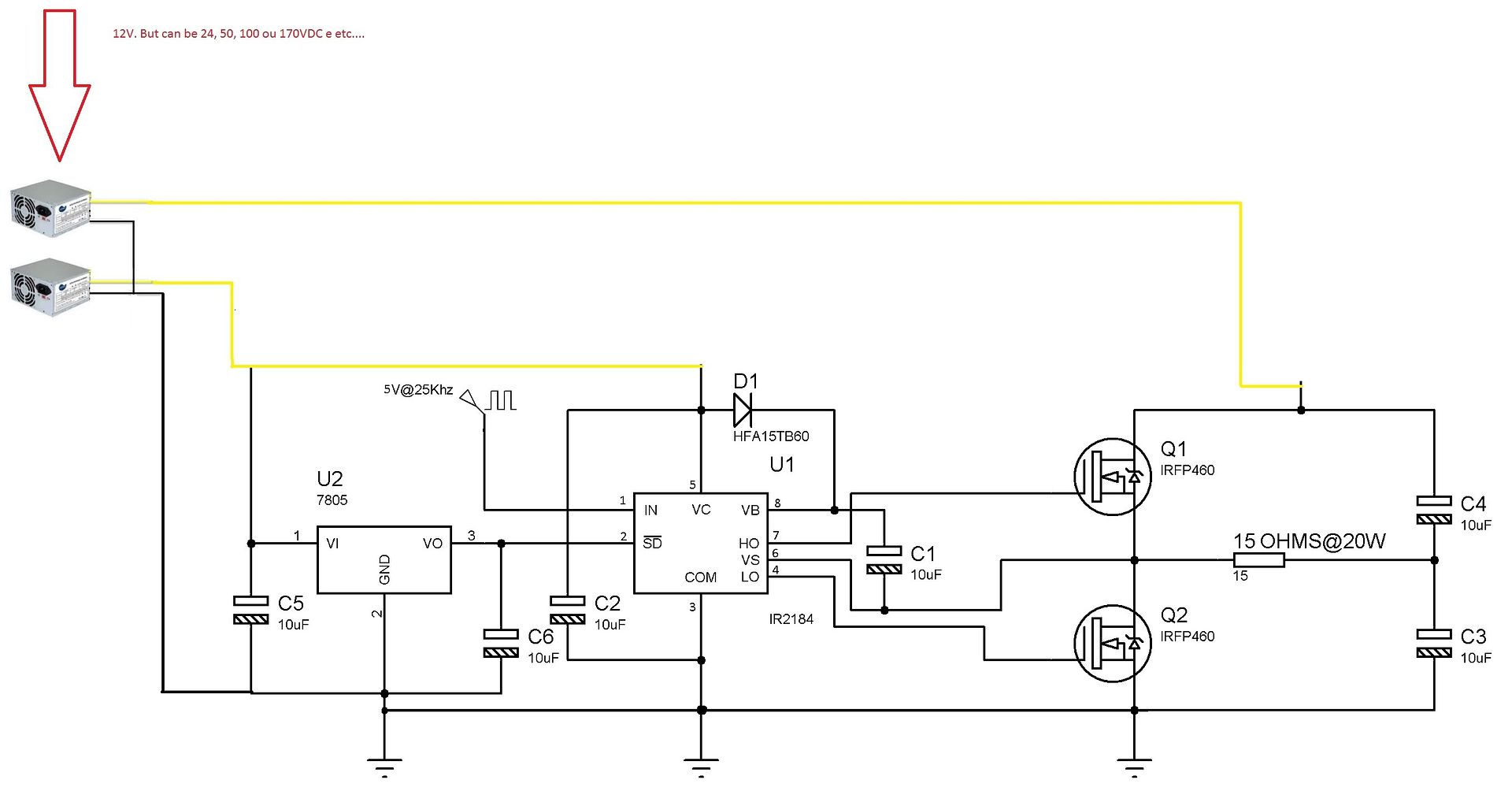
Lets say that I need to work with two separated power supply's. One will be my power supply for the control circuit (12V).
Lets consider that I will use another power supply with 12VDC to power the mosfets and capacitors....
So now I have two power that has different ground lines......
My problem is the COM PIN of the IR2184. Accordingly to the datasheet, I need to connect it to the ground of the "HIGH" power supply. When I say "HIGH" I am referring to the power supply that feeds the mosfets.
In this example, the power supply is 12V, but it can be 24V, 100VDC..... I do not know yet.....
I connect the COM PIN to there and what happened? My IR2184's burned... twice........
What is the correct way to connect the two power supply's and my control circuit?
bye
I am designing an power inverter.
My idea is transform 12VDC in 120VAC@60Hz.
I will make a signal PWM at 25Khz comparing a triangle wave and a sine wave. OK.
But, to make things simpler in the beginning, I am testing with an static square wave at 25Khz provided by a 555 IC.
I threw this signal on a IR2184 gate driver to switch my two IRFP460 mosfets.
So I started with a basic circuit:
This one is working very well. I am using a single power supply with 12VDC. Look the all the power lines and grounds are the same.
The signal at my gate is ~12V. Nice:
And measuring the voltage across the resistor I came with this:
12Vp.p. It looks that is working.
BUT.....
Lets say that I need to work with two separated power supply's. One will be my power supply for the control circuit (12V).
Lets consider that I will use another power supply with 12VDC to power the mosfets and capacitors....
So now I have two power that has different ground lines......
My problem is the COM PIN of the IR2184. Accordingly to the datasheet, I need to connect it to the ground of the "HIGH" power supply. When I say "HIGH" I am referring to the power supply that feeds the mosfets.
In this example, the power supply is 12V, but it can be 24V, 100VDC..... I do not know yet.....
I connect the COM PIN to there and what happened? My IR2184's burned... twice........
What is the correct way to connect the two power supply's and my control circuit?
bye

")


