How do I turn a relay on and off with two momentary switches?

Thread Starter

Jesse Klein

Joined Dec 5, 2014
26
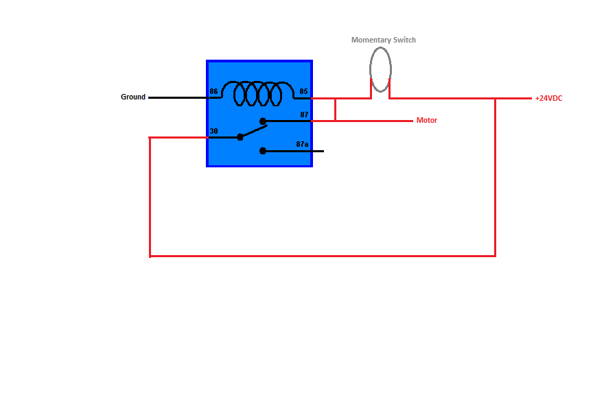
How do I turn a relay on and off with 2 individual momentary switches?

I have an arm that will swing down and land on a momentary switch (we shall call this the "On Switch"), that will trigger the relay and turn on the motor. The motor will rotate the arm back into position. When the arm is fully upright, the bottom on the arm will hit another momentary switch ("Off Switch), that will trigger the relay and turn the motor off.

It is important to note that the "On Switch" should not be able to turn off the relay. Visa Versa, the "Off Switch" should not be able to turn on the relay.


MaxHeadRoom

Joined Jul 18, 2013
28,698
I do not have any idea what anything you just said means.
I will spell it out, you wire a momentary normally open push button for start, and wire a Stop normally closed momentary button in series with this and the relay coil.
Locate a unused normally open contact on the relay and wire this in Parallel with the Start push button.
??
Max.
 
Last edited:

MaxHeadRoom

Joined Jul 18, 2013
28,698
Except that is not the complete schematic, I can post the one you want if necc?
You need a relay with a spare contact on it.
Max.
 

Thread Starter

Jesse Klein

Joined Dec 5, 2014
26
Except that is not the complete schematic, I can post the one you want if necc?
You need a relay with a spare contact on it.
Max.
I think I got it now. I need a DPST Relay, not a SPDT relay. Now I just need to figure out how to turn it off via another momentary switch


MaxHeadRoom

Joined Jul 18, 2013
28,698
The relay coil circuit can be fed from a voltage based on your relay coil, the one you show is 24vdc, the motor supply is based on your motor voltage, with a DC motor, the direction is polarity dependent.
The coil is 0&1, the other contacts are 2&4 and 6&8.
Max.
 

Thread Starter

Jesse Klein

Joined Dec 5, 2014
26
The relay coil circuit can be fed from a voltage based on your relay coil, the one you show is 24vdc, the motor supply is based on your motor voltage, with a DC motor, the direction is polarity dependent.
Max.
Am I an idiot? I still do not understand what you are talking about. Was my last drawing not correct?

I am using 24V power, a 24V motor, so the relay should be 24V. I do understand that DC motors spin forwards if wired one way, backwards if the wired the other way. I only need the motor to spin one direction.
 

Thread Starter

Jesse Klein

Joined Dec 5, 2014
26

So when the "ARM" goes back/down, it will contact the momentary "ON" switch. That switch will turn on the latching relay. which will in turn, turn on the motor. The motor will rotate the "ARM" until it contacts the momentary "OFF" switch. That will unlatch the relay, causing the motor to turn off.

Thats is what I have wired here correct?


MaxHeadRoom

Joined Jul 18, 2013
28,698
It appears to be OK, so these are limit switches, not push buttons? if so they usually have both N.C. and N.O. options, as the OFF button is N.C. as previously stated.
Max.
 

JWHassler

Joined Sep 25, 2013
306
Not to cloud the issue, but if the arms STAYS against the 'off' switch, you'll need this:

upload_2014-12-15_15-11-47.png
... to allow the motor to start when the OFF-switch is still made
 
Top