
Lets slowly....So, I made this circuit:

It is working but not has I want.
Now I can thrigger the FET with 5V, but let me show something:
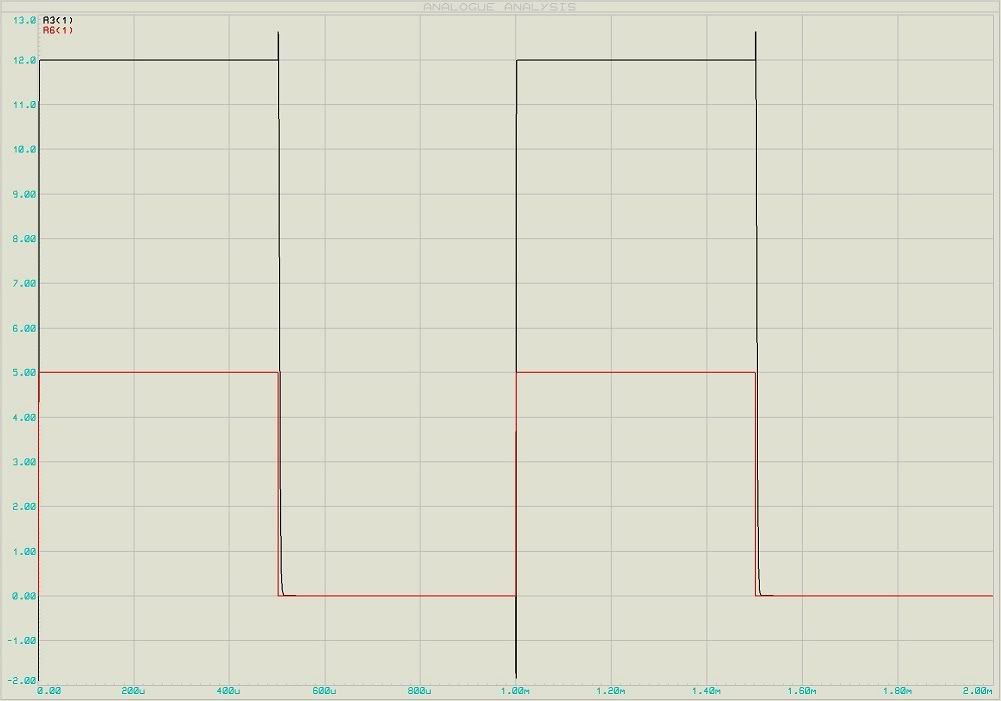
This is the input of 5V and the output with 1Khz:

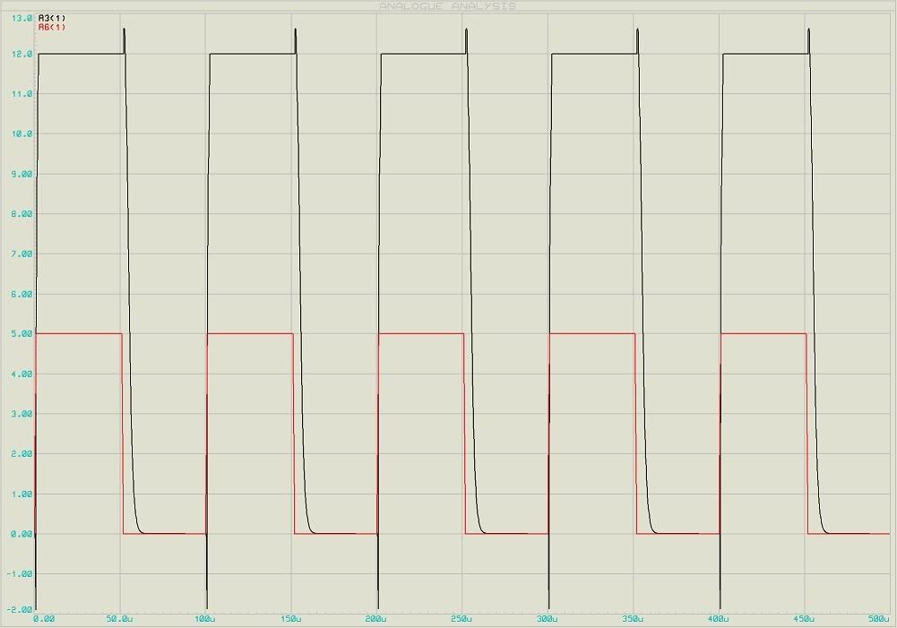
Hum.. It is fine, hun? Ok, let me show now with a 10Khz 5V input:

Still working...
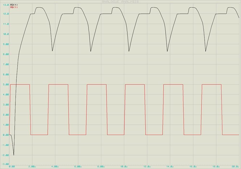
But now with 50Khz, something strange starting to occur:

Here you can see better:

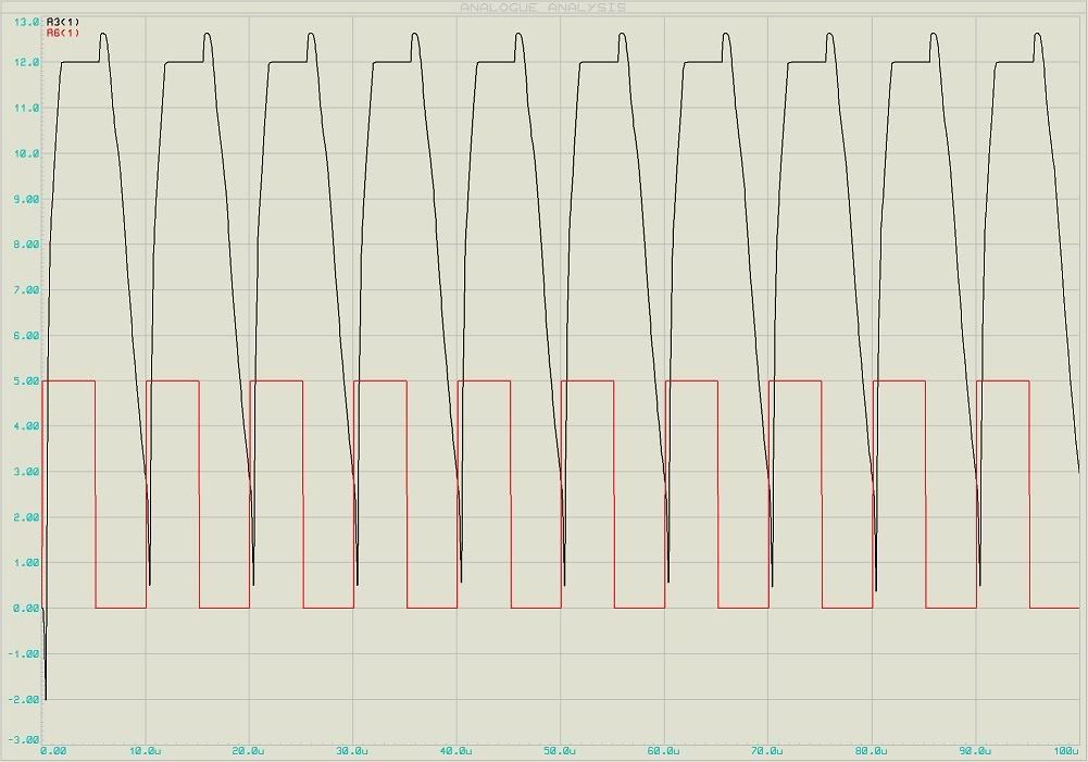
And finally with 400 or 300Khz:

The problem is that the mosfet is still conducting even when I put 0V on the gate. This is taking some time to "discharge" the energy on the gate.
I ploted some cicles of the input to see the voltage on the gate:
5V on the lower transistor and 300Khz:
http://img.photobucket.com/albums/v222/ahhh/Eletronica/vg.jpg
Why? This is causing my problems now.
The project that I using is this one:
http://www.bineco.dk/ellert/smps.htm
The project is not in english, but I can see the circuti and interpret it...
Hope some help.
Thanks again.

It is working but not has I want.
Now I can thrigger the FET with 5V, but let me show something:
This is the input of 5V and the output with 1Khz:
Hum.. It is fine, hun? Ok, let me show now with a 10Khz 5V input:
Still working...
But now with 50Khz, something strange starting to occur:

Here you can see better:
And finally with 400 or 300Khz:
The problem is that the mosfet is still conducting even when I put 0V on the gate. This is taking some time to "discharge" the energy on the gate.
I ploted some cicles of the input to see the voltage on the gate:
5V on the lower transistor and 300Khz:
http://img.photobucket.com/albums/v222/ahhh/Eletronica/vg.jpg
Why? This is causing my problems now.
The project that I using is this one:
http://www.bineco.dk/ellert/smps.htm
The project is not in english, but I can see the circuti and interpret it...
Hope some help.
Thanks again.


