H-Bridge Design

Thread Starter

Falven

Joined Feb 27, 2010
15
Hello,
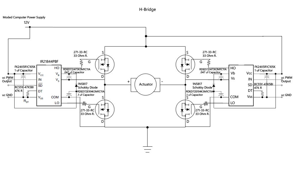
I am pretty new to electronics. I want to design an H-bridge so I may switch a Linear Actuator On/Off and reverse the polarity using a microcontroller. The Motor/Linear Actuator is rated at 12V, 5A on load. The Microcontroller can generate 5V and a Maximum of 40mA to switch the circuit. How many inputs would I require from the Microcontroller? What kind of transistors and with what power ratings should I use?
Thanks
-Falven
 

Felo

Joined Feb 20, 2012
91
Hi, for FFW and REV operations, you can implement with only 2 I/O, for the transistors I would use TIP 1XX, MOSFET should have smallers foot print, use a fast flyback diode across power transistor (some transistor have one in already) do a google search I've got tons of hits. Pick one and if you have anymore questions, come back here.
 

Thread Starter

Falven

Joined Feb 27, 2010
15
Put H bridge in find box, this page, upper right. Consider Sgt Wookie's two SPDT relay H-bridge, assuming actuator has limit switches. http://forum.allaboutcircuits.com/attachment.php?attachmentid=17722&d=1269657559
There are no SPDT Relays that can handle the power specifications I mentioned. What I am confused about is the schematic I would need and the power ratings for the Transistors.
So I can just buy 4 Mosfetts (What power specs?) and set them up in this configuration, no diodes, resistors or anything and it will work reliably? What would be the duty cycle? Keep in mind I have never designed or built an H Bridge or anything similar really before so detailed help would be really appreciated.
-Falven
 

Thread Starter

Falven

Joined Feb 27, 2010
15
What do you mean by this? Are you referring to your 40mA max uC output?
No, what I mean by this is that there are no DPDT relays with a contact rating of 5A and a coild voltage of 12V that can be switched by my 40mA Microcontroller outputs.
I believe a solid-state H-Bridge is my best option, but there are no IC's that can handle my power secifications either, so I need ot build one form scratch.
My qeustion still stands...
Thanks for the help thus far,
-Falven
 

Audioguru

Joined Dec 20, 2007
11,248
All your Mosfets are upside down. They are N-channel so the drain connects to positive voltages. Look at the correct schematic in the datasheet for the Mosfet driver IC.
 

count_volta

Joined Feb 4, 2009
435
Top