Electrect Microphone Circuit?

Thread Starter

crazyengineer

Joined Dec 29, 2010
156
Hey. I want to test out a electrect microphone circuit soon. I understand that the standard electrect microphone produces very small voltage, so I understand that it needs an amplifier. Here's my schematic thus far based on the schematics I've read....


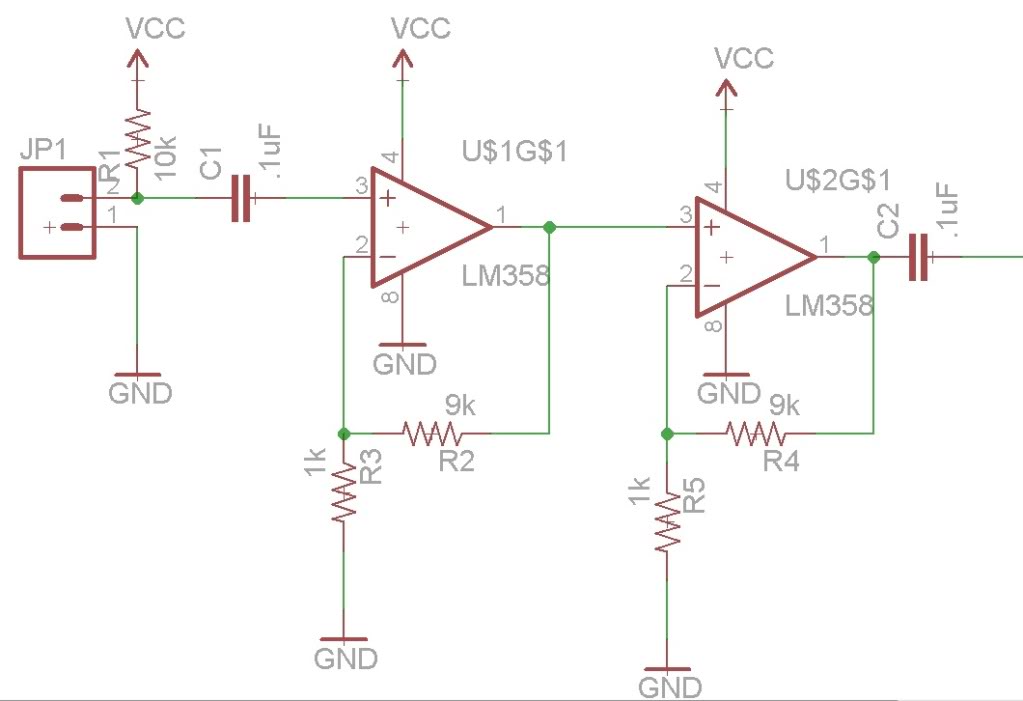
However, there are a few questions I have

1) Is it even necessary to have a cap at the end of the amplifier circuit? Why is it needed.
2) Most designs used inverting omp amps while my design uses non inverting. Is this wrong to do?

Thank you!
 

beenthere

Joined Apr 20, 2004
15,819
Sorry, I just missed the pullup.

That coupling cap is to keep any DC from affecting the power amp. Common practice.

You will have a problem running with a single supply. The mic output will be AC, and may easily clip part of the negative signal excursion. Again, it's common practice to arrange for a virtual ground to offset the op amp about halfway between ground and Vcc so you can handle AC signals. See if this thread helps - http://forum.allaboutcircuits.com/showthread.php?t=51462
 

Thread Starter

crazyengineer

Joined Dec 29, 2010
156
Sorry, I just missed the pullup.

That coupling cap is to keep any DC from affecting the power amp. Common practice.

You will have a problem running with a single supply. The mic output will be AC, and may easily clip part of the negative signal excursion. Again, it's common practice to arrange for a virtual ground to offset the op amp about halfway between ground and Vcc so you can handle AC signals. See if this thread helps - http://forum.allaboutcircuits.com/showthread.php?t=51462
So that's why people use the inverting configuration? To achieve the virtual ground found in the inverting configuration? Also, let me see if I understand this correctly

Since it dips to the negative, you need something to make the negative voltage "just zero" at that point?
 
Last edited:

SgtWookie

Joined Jul 17, 2007
22,230
The LM358 is a very slow opamp; you'll lose a lot of signal (eta: particularly the higher frequencies) with it.

AudioGuru posted this schematic many moons ago; you should use it instead of the circuit you posted:


Note R2 and R3; they keep the opamps' noninverting input signal biased at Vcc/2. The only change that I would suggest for this particular preamp is to either reduce R2 to 68k, or increase R3 to 150k (preferred). This is due to the particular opamp used; the TL07x and TL08x series of opamps cannot "see" within about 3v of the negative rail, nor within 1.5v of the positive rail. Changing R2 or R3 to the values specified will bias the input to about the center of this particular opamp family's range with a 9v supply. This will allow the preamp to continue operation until the battery is nearly dead.

eta: You can use a TL082 if you can't find a TL071; just wire the unused channel as a voltage follower - noninverting (+) input to the other channel's noninverting input, and the inverting (-) input to that same channels' output. This will keep the unused channel from oscillating unpredictably. The TL08x family is basically the same as the TL07x family, but the noise specifications are not as good. You would have a hard time telling the difference though.
 

Attachments

Last edited:

SgtWookie

Joined Jul 17, 2007
22,230
The TL07x and TL08x family of opamps are designed to be used with a dual rail supply. If you are using a single supply, you have to compensate for the lack of a negative supply by using a resistive divider to keep the opamps' input at fairly close to the midpoint of your single supply.

With a single supply opamp that can "see" down to 0v, you will run into a similar problem when the input signal goes below the negative rail; the waveform will be truncated at 0v causing a huge amount of distortion.

But back to the TL071:
As I implied before, this family of opamps can only "see" an input range of voltages that is >= -V +3v, and +V - 1.5v. Since the supply is shown as ground and 9v, that means the input signal needs to be between 0v+3v = 3v and 9v-1.5v=7.5v.

If R2 and R3 are equal @ 100k, then the biasing point will be 9v/(100k+100k)*100k, or 4.5v. However, the center of the actual opamp input range is halfway between 3v and 7.5v, or (7.5-3v)/2+3v = 5.25v, so the bias really should be closer to 5.25v instead of 4.5v.

Simply changing R3 to 150k means the new bias point will be 9v/(100k+150k)*150k = 5.4v, which is plenty close enough.
 

Audioguru

Joined Dec 20, 2007
11,248
The + input of the first opamp in your preamp must have a DC reference voltage that is near half the supply voltage. Your circuit does not have a DC reference voltage so the PNP input transistor of the LM358 will float high and stop the opamps from working.

For audio you should use a low noise audio and low distortion opamp like a TL071 single, TL072 dual or TL074 quad. They also have a frequency response to 100kHz so they play all audio frequencies.

The LM358 and LM324 are older low power opamps that reduce their supply power by having the output transistors without enough current which produces noise (hiss) and crossover distortion.

The non-invereting opamp in my preamp has a high input resistance so its does not load down the fairly high output impedance of an electret mic.
The inverting preamp shown has an input resistance of only 1k ohm which shorts most of the output of an electret mic and is wrong.
 
Top