Dual Power Supply - Potentiometer burns

Thread Starter

tejasdj12

Joined Jul 11, 2010
20
I'm making an Adjustable Dual Power Supply with +V, GND and -V DC output. This is my circuit:

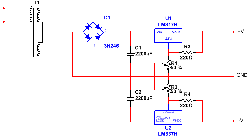
I've used a Center tapped transformer that 18-0-18V output and with 2A rating. I'm using a Full Bridge rectifier with a Capacitor filter. I'm using LM317 for +V regulation and LM317 for -V regulation. Both the voltages can be adjusted with respect to ground using the 10K potentiometers R1 and R2.

Problems:
1. Voltage across each Capacitor shows around 30V
2. No problems while adjusting +V. But, excessive current flows through -V. For example, at 20V +V, the current through R1 is 20mA, whereas, at 20V -V, the current through R2 is 50mA. Current distribution is uneven across regulators LM317 and LM337. But regulator temperatures are normal, not too hot
3. When -V is decreased below 15V, the R2 potentiometer burns and the current through it is about 120mA
4. The output is not completely regulated. Even if I adjust a fixed voltage, the output voltage slowly starts decreasing. Like, I adjusted +5V and after around 10 mins, it was +4.45V. I even checked the input voltage across LM317 and it was constant.
 

bertus

Joined Apr 5, 2008
22,278
Hello,

I do not see the decoupling capacitors in your schematic.
In the datasheet is given that a 0.1μF capacitors are used at the input and output of the regulator.

Here are both the datasheets:
LM317
LM337

Bertus
 

crutschow

Joined Mar 14, 2008
34,465
As bertus noted, you need capacitors 0.1μF on the input and output. The outputs also needs at least a 10μF electrolytic. Otherwise you may get oscillations that could cause the type of behavior you've noted.
 

Thread Starter

tejasdj12

Joined Jul 11, 2010
20
1. Okay, I tried adding a 0.1uF Ceramic Cap and 10uF/63V Electrolytic parallel across V+ and GND. Still, output continues to drop.
2. If I add any load (say, an LED with 220Ω resistor). There's again some drop in the output voltage. If I add another LED and 220Ω in parallel, voltage further drops. Likewise, when I add 3 such LEDs, my output voltage dropped from 5V to around 4V.
3. Is it okay that my 2200uF capacitor has a voltage rating of 25V, even though Rectifier output voltage reaches 30V. I mean, is it safe?
4. I still have no clue why LM337 is passing out so much current. I've tried adding a 710Ω resistor in series between Rectifier output and LM337 to limit the current. It does help, but again, how does it work all fine with LM317

@atferrari: Does it really matter if I use a 220Ω resistor? After all it depends upon the ratio of R3 and R1
 

atferrari

Joined Jan 6, 2004
4,771
@atferrari: Does it really matter if I use a 220Ω resistor? After all it depends upon the ratio of R3 and R1
That resistor sets the load current for the regulator.

According to datasheet there is a minimum to ensure that the regulator does its job. For the 217 and 317 it should be 10 mA. For the 117: 5 mA.

Read the datasheet to se how it relates to the 1.25V reference voltage.
 

praondevou

Joined Jul 9, 2011
2,942
1. Voltage across each Capacitor shows around 30V
Not ok if the maximum rating is 25V. Do not exceed the maximum rating for a prolonged time.

3. When -V is decreased below 15V, the R2 potentiometer burns and the current through it is about 120mA
What is the power rating of the potentiometer?
How did you measure the 120mA? Isn't the maximum adjustment pin current 100uA? How can there be 120mA through R2 with R4=220R at 15V V-?

4. The output is not completely regulated. Even if I adjust a fixed voltage, the output voltage slowly starts decreasing. Like, I adjusted +5V and after around 10 mins, it was +4.45V. I even checked the input voltage across LM317 and it was constant.
Looks like something is heating up over time, could only be something like 10 to 20 degrees temperature change. Most likely the potentiometer since it's the one that burns.
 

crutschow

Joined Mar 14, 2008
34,465
Beginning to think either sometime is connected wrong or you have a bad regulator. Have you double checked the pinouts and all the associated circuitry wiring.

What is the value of R1 and R2?
 

Thread Starter

tejasdj12

Joined Jul 11, 2010
20
Beginning to think either sometime is connected wrong or you have a bad regulator. Have you double checked the pinouts and all the associated circuitry wiring.

What is the value of R1 and R2?
Yes, everything is connected properly. I've doubled checked the pinouts and even tried connecting circuit for the second time. I did suspect a bad regulator. But, I had a fixed 12V DC supply, and I tried to get a constant voltage at the output using regulators (both LM317 and LM337), and it did give. No voltage drops, nothing.

R1 and R2 both are 10K presets

Not ok if the maximum rating is 25V. Do not exceed the maximum rating for a prolonged time.

What is the power rating of the potentiometer?
How did you measure the 120mA? Isn't the maximum adjustment pin current 100uA? How can there be 120mA through R2 with R4=220R at 15V V-?

Looks like something is heating up over time, could only be something like 10 to 20 degrees temperature change. Most likely the potentiometer since it's the one that burns.
Somewhere I read that Electrolytic Capacitors can work at even twice its voltage rating. That's the thing, I feel, is the root of the problem. I'll be getting some 2200uF/45V Caps within a few days. Hope it helps

Power rating is 0.25W for the Pots and all the resistors.

I connected my Multimeter (MilliAmmeter) between the Pot and GND to measure the current through the Pots. And not just 120mA, today I got around 190mA through R2 at 2V output (between V- and GND). Strangely, even at the same output voltage (between V+ and GND), current through R1 didn't even cross 50mA :eek:

Yeah, I did notice that. LM317 was quite hot after about 5 mins of use. But only R2 burns. I never had problems with R1. I tried replacing R2. But still not working.

Damn, I need to get this thing working before February. :mad:
 

bertus

Joined Apr 5, 2008
22,278
Hello,

The current through the potentiometers can not be that high.
The current through the potentiometers will be constant and have a value of Vref / (the resistor between Vout pin and the adj pin)+Iadj.
Iadj has maximum value of 100 μA given in the data sheet.
I your case 1.25 V / 220 Ω + 100μA = 5682 + 100 μA = 5782 μA.

There MUST be something wrong in your connections.

Bertus
 

crutschow

Joined Mar 14, 2008
34,465
I agree that either you have a bad part or something is connected wrong.

Read the voltages at all the connection points to ground and post them on the schematic.
 

Thread Starter

tejasdj12

Joined Jul 11, 2010
20
I should jump off a cliff and die :mad:

Sorry for the trouble folks, it was my STUPIDEST MISTAKE!
Obviously, Wrong Pinouts! :mad:
Most of you were correct at the first statement

I mistook LM317 and LM337 with fixed voltage regulators like 78xx

For LM317 and LM337, the pinouts are like:
1. Adjust
2. Output
3. Input

And for 78xx:
1. Input
2. Ground
3. Output

My Bad! Sorry for wasting your time and energy.
And a big Thank You for all your precious help

By the way, my LM337 is completely damaged. So, I think I would need another trip to the store.

A final question, should I use a fan for cooling along with Heatsinks? Because, the input voltages would be ~30V and output might be as small as 2V. For sure, regulators would burn at that high temperature. The reason I would avoid adding one is, it would complicate the circuit a bit and also increase the overall cost
 

crutschow

Joined Mar 14, 2008
34,465
A regulator with no heatsink can dissipate no more than a few watts even with a fan, which corresponds to a maximum output current of about 0.1A. So if you want an output of say 1.5A maximum you will need a heatsink capable of dissipating at least 45W for each regulator. To keep the size small you could mount them on a fan cooled PC CPU type heatsink.
 

takao21203

Joined Apr 28, 2012
3,702
Use LM2576 + $2 VGA cooler.

You can either mount the LM2576 upside down, or glue it to the cooler with epoxy or silicone cement.

If you want the LM2576 chips on the PCB you need two holes for the cooler.

With small VGA coolers you can get full 3 Amps from these chips. The fans need 12V or if you don't need full current, you can run them with 7V to 9V.

I have years of experience with the technology.

I think in theory the chip also can be used for negative supply.

The linear chip you use is 40 years old technology. More than 1/2 Amps, and you get a problem to cool these.
 

Thread Starter

tejasdj12

Joined Jul 11, 2010
20
Thank you Bertus!

@takao21203
I've already bought the components :(
I'll use yours next time I build any other power supply

I'm facing another problem now. The regulator works just fine. But now, when I adjust an output voltage, momentarily it stays constant but starts decreasing later on. What I read somewhere is, its due to the Thermal drift of the potentiometer. I'm currently using a Preset so that the circuit becomes compact and simple.
Should I switch over to a potentiometer or get another preset with higher power rating?
 

crutschow

Joined Mar 14, 2008
34,465
Is the output loaded? If the slow change only occurs when you lower the voltage, then that's likely do to the large output capacitance slowly discharging through the voltage adjust resistors. Thermal drift of the potentiometer is very small and not likely a problem.
 

Thread Starter

tejasdj12

Joined Jul 11, 2010
20
Is the output loaded? If the slow change only occurs when you lower the voltage, then that's likely do to the large output capacitance slowly discharging through the voltage adjust resistors. Thermal drift of the potentiometer is very small and not likely a problem.
No, its just an LED with 1.5k resistor.

This is the post I'm talking about:
http://electronics.stackexchange.co...power-supply-output-takes-a-while-to-stablize

There, the OP said that:
UPDATE: Replaced the 5K pot (which was a crappy single-turn rated at 50mW) with a 5K 10-turn precision pot (rated at 2W). Now I can crank it up to, say 5V or 12V or whatever and my DMM shows a stable reading right away.
Out of all those, the only answer I felt was correct is:
Given the information provided by your data logger's diagrams, I am fairly sure you are looking at thermal drift. The time constant of your drift is in the range of some 10 seconds to some minutes, which is quite common for thermal settling of small-ish parts. You say that in your first tests, your load takes something like 0.1 A, and the difference between input and output is approximately 20 V - 5 V = 15 V. This means your LM317 is dissipating apporximately 1.5 W - enough to give it a noticeable temperature rise, depending on the heatsink. When you set the output to a higher voltage, and assuming the current stays the same, you reduce the power dissipation (heating action), which would explain why the drift takes longer with a higher output voltage. (Edit: Slightly different numbers would apply for your experiments with a 1k load resistor, of course.)
 
Top