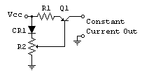
constant current source

Thread Starter

unlv007

Joined Apr 5, 2008
44
I need a constant current source that can produce constant current from 1mA to 50mA. The load is resistve equal to 10K. Could someone please recommend some good current sources that i could buy? Also, if i want to make them using resistors, transistors etc how to do so- any tips?
thanks
 

hgmjr

Joined Jan 28, 2005
9,027
I'm fond of this approach that uses an opamp and an BJT or if you have a high enough DC voltage power source you can use a mosfet transistor.

hgmjr
 

Audioguru

Joined Dec 20, 2007
11,248
Hi Hgmjr,
Sorry but your "contant current source" is actually a constant current sink. A PNP transistor is used in a constant current source circuit.

Years ago, a current regulating diode was sold. It was just a jFET with 2 wires.
 

hgmjr

Joined Jan 28, 2005
9,027
Hi Hgmjr,
Sorry but your "contant current source" is actually a constant current sink. A PNP transistor is used in a constant current source circuit.

Years ago, a current regulating diode was sold. It was just a jFET with 2 wires.
You have a good point.

I was thinking of source in the generic sense such as a voltage source.

hgmjr
 

Thread Starter

unlv007

Joined Apr 5, 2008
44
I've posted this one before, it requires a regulated power supply. A darlington would work better though. R1 set the total range.


Another way of doing it...
is the 317 device a "LM 317" variable voltage regulator? My current souce should provide up to 50mA and have a compliance voltage of at least 50V? Is 50V compliance possible in above circuit?
 

Wendy

Joined Mar 24, 2008
23,421
That depends entirely on the transistors you use, there are plenty that would do it. You can even get a darlingon prepackaged, such as a TIP105. If you do use a darlington, use two diodes instead of CR1, or replace it with a second variable resistor to set the minimum current.

Yes, the 317 is an LM317.
 

Thread Starter

unlv007

Joined Apr 5, 2008
44
is the 317 device a "LM 317" variable voltage regulator? My current souce should provide up to 50mA and have a compliance voltage of at least 50V? Is 50V compliance possible in above circuit?

please give me the link for your former post where you posted the above circuit. I want to understand how the first circuit you made provides constant current.

To set the compliance voltage =50V you recommend trying different types of transistors. So that means i should use the circuit diagram 1, not the LM317 which has inbuilt fixed transistor.
 

SgtWookie

Joined Jul 17, 2007
22,230
well, the lm317 will have a minimum current of 10ma.

an lm317lz will have a minimum of 5ma output.

i'm using a circuit similar to what bill marsden posted, except r1=fixed, r2=variable. for cr1 i'm using just a standard red led, r1 = 5.1k, r2=1k 10-turn bourns knobpot, and q1 = 2n4403. current is from under 1ma to well over 50ma. a log or audio taper pot would be more convenient than a linear pot. however, the 2n4403 is limited to 625mw, so a different transistor would have to be used if the supply voltage were going to be over 10.41v for a 60ma supply.

in order to get a 50ma current through a 10k ohm load, you will need to use a 500v supply.
e=ir
e=0.05 x 10,000
 

Thread Starter

unlv007

Joined Apr 5, 2008
44
please assume that the load is 1K not 10K as i mentioned, so that i need only a 50v supply.
please explain the basic concept behind bill marsden or sgtwookie's circuit. how they act as constant current sources?
thanks.
 

Wendy

Joined Mar 24, 2008
23,421
The resistor on the emitter is going to be the collector current plus the base current. Since the base current is considered negligable the emitter current equals the collector current. The voltage on the emitter resistor remains constant, so it is a constant current source.

Bipolar transistors are fundimentally a constant current device any time there is an emitter resistor.
 

SgtWookie

Joined Jul 17, 2007
22,230
cr1 maintains a relatively constant voltage across itself.
in bill marsden's circuit, the emitter resistor sets the maximum current.
the pot on the base limits the current through cr1, and controls the base current.
current control is reasonably linear, but the minimum current is roughly 8 percent of the maximum current. decreasing the current further requires an increase of the emitter resistor.

in my variation, the control is more logarithmic. as the emitter resistor decreases, current via the emitter ramps up dramatically. this can make accuracy problematic in the higher current ranges. power dissipation in the pot and transistor are other problems if the supply is much over 10v
 

Wendy

Joined Mar 24, 2008
23,421
The way to overcome power problems on the potiemeter is to up its value, say to 10Kohm or 100Kohm, but then you have to compenstate by upping the gain of the transistor. A darlington triplet wouldn't be a bad idea in this case. If the pot is linear the setting should be too.

Something else that needs mentioning. If the LM317 is never short circuited on the output with the 50V input then it should be OK too, as it is a variable resistor in this configuration and only drops what it needs to to regulate the current. If the voltage on the output never goes below 20V then it would work fine.
 

SgtWookie

Joined Jul 17, 2007
22,230
bill,
the reason that your circuit is not entirely linear is because the gain of the transistor changes as the current through it changes. usually, the gain starts out at some median value with low collector current, and increases as collector current increases up to some point, then falls off as saturation approaches.

in the case of a 2n3906 at room temperature, hfe may be 110 at 0.1ma, peaking at around 135 between 4 and 10ma, and then start falling off. by 40ma, it's down around 125 and under 100 by 80ma. but between 5 and 15 ma, it will almost be linear.
 

Wendy

Joined Mar 24, 2008
23,421
It would be interesting to graph it, I know there is a nonlinear area where the bias falls below the base emitter threshhold, but I'm not sure what it would look like.

I'm thinking of building it's complimentary twin (the current sink) in the near future for a variable load. It's an easy project, and can be useful.

The darlington configuration will compensate for some of that, and add other factors.
 

SgtWookie

Joined Jul 17, 2007
22,230
i downloaded a 2n3906 datasheet from national semiconductor's site. it has the hfe plot in it. i would post it, but my capslock and control keys stopped working, and so i'm having trouble doing things like screen prints.

OK, now I've attached the plots for the 2N3906.
 

Attachments

Thread Starter

unlv007

Joined Apr 5, 2008
44
That depends entirely on the transistors you use, there are plenty that would do it. You can even get a darlingon prepackaged, such as a TIP105. If you do use a darlington, use two diodes instead of CR1, or replace it with a second variable resistor to set the minimum current.

Yes, the 317 is an LM317.
please explain how darlington helps to set the compliance voltage to 50V and why should i use two diodes instead of 1, as you recommend?
thanks
 

Wendy

Joined Mar 24, 2008
23,421
The issue here is gain, transistor gain. A darlington looks like one transistor with a higher Base Emitter drop (which explains the two diodes, which are there to imitate the Base Emitter drop and eliminate it from the adjustment). If you have a large voltage you don't want to heat up the potentiometer, preferably even a little, so you have to up its resistance. Too high a resistance on the pot means the transistors gain gets involved, which is why a darlington is good. If each transistor has a beta (gain) of 50 the darlingtons total gain is 2500. One ma in the base causes 2.5 A at the collector.

All About Circuits eBook has a section on Darlingtons here. http://www.allaboutcircuits.com/vol_3/chpt_4/6.html

If you want I would be glad to draw what I visualize the circuit would look like, and go over the theory specifics in more detail with the drawing. This is one of the areas in electronics that is fascinating to me.
 

Thread Starter

unlv007

Joined Apr 5, 2008
44
The issue here is gain, transistor gain. If you have a large voltage you don't want to heat up the potentiometer, preferably even a little, so you have to up its resistance. Too high a resistance on the pot means the transistors gain gets involved, which is why a darlington is good. .
I understood your explanation for two diodes use, but please explain why you want to up the resistance and how darlington amplifier helps. :confused: so please explain with some detail because many things are obvious to you but not to me! I am much less experienced.
 
Top