Hi guys, this is my first post so first off an introduction. I live in Vancouver, BC, Canada and I work as a network engineer and computer teacher, but in my free time I have been working to set up a computer museum for many years now. Now, here's why I am posting.
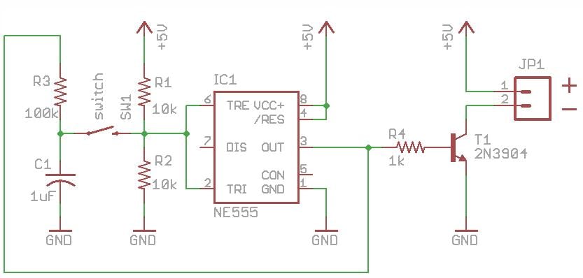
I am building a tower case for my Atari STe, and the case I have chosen to use is an ATX case, and as such has a momentary pushbutton as a power switch. I am going to modify an ATX power supply to drive the STe, but an ATX power supply requires a pin on the ATX connector to be latched to ground to turn the power supply on, and opened to turn it off. So I am looking to build a simple circuit to connect to the power button, the on/off line, ground, and the +5v trickle line from the atx supply so that when I push the power button the power on line is latched to ground to power up the system and when I push it again the connection is broken and the supply shuts down. I know this can be done simply, but I'm a little rusty with my low level logic. Can someone help me out with this? Thanks guys!
I am building a tower case for my Atari STe, and the case I have chosen to use is an ATX case, and as such has a momentary pushbutton as a power switch. I am going to modify an ATX power supply to drive the STe, but an ATX power supply requires a pin on the ATX connector to be latched to ground to turn the power supply on, and opened to turn it off. So I am looking to build a simple circuit to connect to the power button, the on/off line, ground, and the +5v trickle line from the atx supply so that when I push the power button the power on line is latched to ground to power up the system and when I push it again the connection is broken and the supply shuts down. I know this can be done simply, but I'm a little rusty with my low level logic. Can someone help me out with this? Thanks guys!


