Can a 3000 watt inverter be repaired?

Thread Starter

sdowney717

Joined Jul 18, 2012
711
I destroyed the inverter.
It is 3000 watt continuous MSW.

I accidently put 120 VAC grid power into the on-off switch circuit. I was hooking up an external on-off switch.

There are 2 main boards. On each board a 25vdc electrolytic capacitor exploded.
On one board a SMD transistor burned and a short section of copper tracing.
On other board a large power transistor of some type burned. that one is part of a long line of transistors screwed into a very large heat sink.

How do you replace an obliterated SMD transistor? Can a standard transistor be substituted- wired into the board, if so what type to use?

What do you think? I can post pictures tomorrow of the various areas that have obvious damage.
 

eng_stu

Joined Jan 29, 2012
13
I think you will be hard pressed to figure out what transistors to replace them with. The one that shares the heat sink could possibly be the same as the others on the heat sink. Also if its feeding back into the grid there will be legal ramifications with repairing it. You might be able to order replacement board/s from the manufacturer. Also, if you can find someone with the same model you can copy down the transistor text on the IC to find a replacement (ie post your part number here).
 

BSomer

Joined Dec 28, 2011
434
I think that it most likely can be repaired. It is dependent on how badly the PCB was damaged and like eng_stu stated, if you can identify the bad parts. Further help will be available with good, clear pictures of the PCB and close ups of the damaged area. Before you take pictures of the board though, clean it thoroughly with isopropyl alcohol.
 

Thread Starter

sdowney717

Joined Jul 18, 2012
711
Ok, identities of obviously blown items

Mosfet F1010E, a whole line of these. One is obviously destroyed. Clamp for attaching to heat sink seriously heated which discolored outer case of mosfet next to burned mosfet


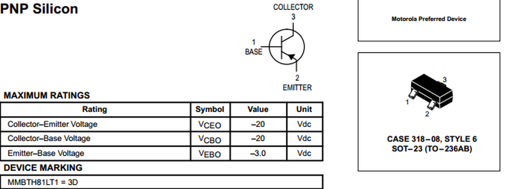
3D SMD transistor or 3B? only exists on one board.
need help id that part. perhaps can use a substitute trans?


two 220uf 25vdc electrolytic capacitors, one on each board
I found the outer blown covering for ID

 
Last edited:

Thread Starter

sdowney717

Joined Jul 18, 2012
711
Inverter model is PKCOAW
made by 'PEAK'

resistor yellow-purple-gold-gold next to mosfets


two blown traces next to power on-off switch connector. Since power surge hit there, is the cause I think. It does not look like a SMD device was there.


Attachments

Last edited:

t06afre

Joined May 11, 2009
5,934
For the 3x transistor take a look at the PDF file. It may offer some help. The burned tracks may be repaired with a wire. From solder joint to solder joint. Perhaps a bit tricky on the SMD but doable. If the IRF1010E component is cheap. I would have considered replaceing them all.
 

Attachments

Thread Starter

sdowney717

Joined Jul 18, 2012
711
I called Allied Electronics.
Tech guy says the 3D is equivalent to a MPSH81 or generic NTE395
http://www.fairchildsemi.com/ds/MM/MMBTH81.pdf
If it is 3B then it is FMMT918 or a 2N918

It looks more like '3 D' than '3 B'

I was thinking you could drill tiny holes and pass the leads in to solder.

F1010E = IRF1010 and are $2.29 each.

What ohms is a yellow-purple-gold-gold resistor?
http://samengstrom.com/24614782/en/read/4_Band_Resistor_Color_Codes?history=5107960
4.7 ohms
This is only calc online I found that works
 
Last edited:

Thread Starter

sdowney717

Joined Jul 18, 2012
711
I need some help determining whether it is a 3B NPN or 3D PNP transistor

I drew out a diagram showing the schematic how the trans connects to an electrolytic capacitor. one lead of the trans directly connects to the negative side of the capacitor

which way is the polarity for lead 2? It will differ if it is NPN or PNP


Thread Starter

sdowney717

Joined Jul 18, 2012
711
Looking some more, the trans collector is attached to the negative side of a 100 uf capacitor

Emitter connects to negative side of a 220uf capacitor

So will this then be a NPN 3B transistor? (FMMT918 or 2N918)
Meaning it is a 3B NPN transistor?
 

Thread Starter

sdowney717

Joined Jul 18, 2012
711
I found a similar looking circuit using NPN and electrolytics on emitter and collector. I notice that the positive lead of the caps goes toward the NPN transistor E and C


http://www.g3oou.co.uk/newsletterjune.html

Which means the reverse would be true, the negative lead to E and C if transistor was PNP? So then would be a 3D for me.

If anyone can help me out on this?
 

Thread Starter

sdowney717

Joined Jul 18, 2012
711
I drew more of the schematic
It appears this unknown 3? SMD trans drives the piezo buzzer.
I used the polarity as listed on board and components.


So is trans NPN or PNP?
 

Thread Starter

sdowney717

Joined Jul 18, 2012
711
I am pretty sure now it is NPN. I checked the bat neg power terminal to that emitter point on the circuit board and get 0.2 ohms.

I was thinking of using a NTE199 NPN trans since I have one.
 
Top