BMW D12 Marine Diesel rectifier/regulator project

Thread Starter

Pauli

Joined Jun 12, 2012
9
Hi, this is my first post.

I have an old sailing boat with BMW D12 marine diesel. The engine has a generator (or magneto) with brushless permanent magnet rotor and stator with coils. The problem is the rectifier/regulator that blows up about after three years usage. The part costs 200€ and it's hard to find thanks to the engine's old model. I have planned to make it myself.

The rectifier/regulator parts are in a small aluminium heat sink box filled with epoxy. It's impossible to fix or even identify the components. I have find the circuit from the engine's workshop manual. The components are shown without values. The generator's charging capacity is 14 V 350 W - 25 Amps.

Can someone kindly help me to find right components for the rectifier/regulator? I have not very good skills in planning electronics but I can make and solver the unit myself if I get some help with finding components.


Magneto rectifier regulator circuit:


Stator AC output voltage between different wire pairs and rpms:


Original BMW electric diagram:


Picture of the stator:


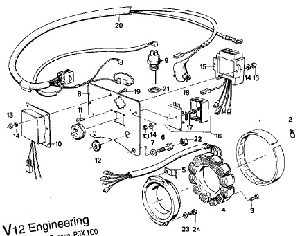
Charging components, a picture from the workshop manual. The rectifier/regulator is number 15


shortbus

Joined Sep 30, 2009
10,045
Being a permanent magnet alternator, the regulator just turns the excess voltage into heat. They are called "shunt regulators". No mater if you build your own or buy a new one, to make it last you MUST make sure that it gets enough air flow over it. And that its mounted to a metal heatsink, the bigger the piece of metal the better. Heat is the biggest problem to this type regulator.
 

crutschow

Joined Mar 14, 2008
34,432
It's difficult to determine the exact part values without know more details about the circuit operation. It would have to be an educated guess.

D1 and D2 are power rectifiers that convert the alternator AC voltage to DC. They should rated for at least 50A and 50V.

D4 is an SCR that shunts the current to ground from the Red winding to kill the output voltage when the battery reaches the charge voltage. I estimate it should have a rating of at least 25A and 250V

D3 appears to be a zener diode that determines the point at which D4 turns on. You may have to experiment to determine the correct diode voltage. I would think about 13V-13.5V would give you near a 14V output.

R1 limits the gate current to the desired value. Its value depends upon the selected SCR characteristics.

R2 shunts an gate leakage current to ground. A few hundred ohms should work for that.

C1 filters the AC control signal. That could be anywhere from 0.1μF up to several hundred μF.

The rectifiers and SCR need to be mounted on a good heat sink, of course.

Has your present regulator failed? If not I suggest adding a small fan (such as a computer fan) to blow directly on the regulator to help keep it cool. That should greatly extend its life. If it's mounted in a hot area near the engine, moving it to a cooler spot if possible, should also help.
 

Thread Starter

Pauli

Joined Jun 12, 2012
9
Thanks for your answers, shortbus and crutschow. Your remarks for cooling are noteworthy! Maybe I use a tiny processor fan with a heat sink.

I got an answer at a finnish electronic forum, too. The electronic hobbyist advice me to ask some professional before I begin to solder parts together. He was not sure of R1 value and SCR, in particular SCR's gate sensitivity.

What do you think about this proposal?

D1, D2 - STPS80170CW STMicroelectronics | 497-4815-5-ND | DigiKey
- Dual center tab Schottky rectifier, 2 x 40 A, 170 V

D4 - S6070WTP Littelfuse Inc | S6070WTP-ND | DigiKey
- SCR, 70 A, 600 V, gate sensitivity 50 mA

D3 - 1N6002B-TP Micro Commercial Co | 1N6002B-TPMSCT-ND | DigiKey
- Zener diode, zener voltage 12 V, 42 mA, 500 mW

R1 - 47-100 Ω
R2 - 1 kΩ
C1 - 1 µF
 

crutschow

Joined Mar 14, 2008
34,432
Thanks for your answers, shortbus and crutschow. Your remarks for cooling are noteworthy! Maybe I use a tiny processor fan with a heat sink.

I got an answer at a finnish electronic forum, too. The electronic hobbyist advice me to ask some professional before I begin to solder parts together. He was not sure of R1 value and SCR, in particular SCR's gate sensitivity.

What do you think about this proposal?

D1, D2 - STPS80170CW STMicroelectronics | 497-4815-5-ND | DigiKey
- Dual center tab Schottky rectifier, 2 x 40 A, 170 V

D4 - S6070WTP Littelfuse Inc | S6070WTP-ND | DigiKey
- SCR, 70 A, 600 V, gate sensitivity 50 mA

D3 - 1N6002B-TP Micro Commercial Co | 1N6002B-TPMSCT-ND | DigiKey
- Zener diode, zener voltage 12 V, 42 mA, 500 mW

R1 - 47-100 Ω
R2 - 1 kΩ
C1 - 1 µF
Those devices generally look OK. But to generate a 50 mA gate current you would need 2.4V-5V across R1 which is a bit much for proper voltage regulation. You likely need to drop R1 to 10Ω or less. A sensitive gate SCR might be better but I don't know if anyone make ones that carry sufficient current for your application.

A small computer fan with an attached heat sink should be fine if you mount the SCR and diodes on it.
 

#12

Joined Nov 30, 2010
18,224
I calculate 10 ohms for R1 (1 volt at 100 ma) and 270 ohms for R2.
This is based on 1.35 Vgt because in the real world, SCRs never use the highest guaranteed turn on voltage or the highest rated turn on current to get started.
These numbers also show that a zener of 11.65 volts is about right.

You will have to muck about with R2 to get this perfect because of the 5% rating on the zener diode and the "real" turn on current and the "real" turn on voltage of the SCR. You can also buy a 2% zener @ 200 Centigrade for 15 cents American at Mouser. Point is, better accuracy is not terribly expensive. You've already done well in choosing semiconductors that are over qualified for the job. Now it's down to fine tuning the trigger voltage.

Search at Mouser shows lack of sensitive gate SCRs until the voltage rating is useless.

This is a good time to autopsy the old regulator to find the real values that were used.

Extra cooling is the key to survival!
 

Thread Starter

Pauli

Joined Jun 12, 2012
9
This is a good time to autopsy the old regulator to find the real values that were used.
The heat sink box is filled with epoxy and it's hard like concrete. Several years I tried to autospy one blown regulator without luck.
 

crutschow

Joined Mar 14, 2008
34,432
The heat sink box is filled with epoxy and it's hard like concrete. Several years I tried to autospy one blown regulator without luck.
There are various epoxy removers available, but I don't know how well they would work on your particular type of epoxy. Might be worth a try.
 

cork_ie

Joined Oct 8, 2011
428
Hello OP,
I am very familiar with these rectifier regulators, and yes you are correct they are cursed by failure due to overheating.
You have already got good advice on how to build a replacement. If you want to keep your unit cool can I suggest the following trick which I have used with great success.

The aluminium casing of the original rectifier regulator unit is finned. Get some thin copper sheet (20 gauge or 0.8mm) about 2" longer than the overall height of the rectifier(1" top and 1" bottom) and fold it several times in a zig zag fashion so that the copper folds fit in between the fins of the rectifier. Leave about 2" of the copper sheet extend at each side, then wrap these copper ends around a short piece of stainless steel pipe and tighten with two hose clips (top and bottom). You will need to paint the aluminium and copper to prevent corrosion between the two dissimilar metals due to salt and humidity. Finally route your cooling water feed through the piece of stainless steel pipe and you will have more than adequate cooling. It is a one hour job at most and will last for years.
 

crutschow

Joined Mar 14, 2008
34,432
...........................

Also a zener shunt regulator LM431 instead of the fixed zener D3 and a trimmer to adjust voltage exactly.
Your suggestion of an LM431 adjustable shunt regulator (which acts like an adjustable zener) in place of the zener is a good idea. It also has a low temperature coefficient rather than the undesirable positive coefficient of a standard 12V zener.

Below is a schematic using that with some best guess resistor values. I also added a transistor emitter follower to increase the gate sensitivity and minimize the current through the LM431.

I do believe the design is coming into focus. :D

Edit: On second thought R3 should be around 30kΩ, not 40kΩ. That will give a minimum zener voltage of about 10V with R5 set to maximum resistance.

SCR Trigger Ckt.GIF
 
Last edited:

Thread Starter

Pauli

Joined Jun 12, 2012
9
I ordered parts from Digikey. First I make a basic model with a 12 V zener. I also ordered couple of LM431 for making an "advanced model".

I hope I can post results and pictures before midsommer eve.
 

Thread Starter

Pauli

Joined Jun 12, 2012
9
Rectifier/regulator done! I really appreciate your help!!! :)

Parts:
D1, D2 - STPS80170CW STMicroelectronics | 497-4815-5-ND | DigiKey
- Dual center tab Schottky rectifier, 2 x 40 A, 170 V

D4 - S8065KTP Littelfuse Inc | S8065KTP-ND | DigiKey
- SCR, 65 A, 800 V, gate sensitivity 50 mA

D3 - 1N6002B-TP Micro Commercial Co | 1N6002B-TPMSCT-ND | DigiKey
- Zener diode, zener voltage 12 V, 42 mA, 500 mW

R1 - 10 ohm
R2 - 270 ohm
C1 - 1 µF film cap.


Aluminium housing (a piece of a cable tray) with a processor cooler (I found these parts in my carage). Using screw terminals give it flexible way to change components.


Charging works fine on slow engine rounds (about 1000 RPM).


Regulator generates a little bit too much voltages on high (2500 RPM).


15 V is too much. An ideal would be 14,5 volts. Any ideas??
 
Top