I'm just a dilettante. My simulation doesn't even have a real microphone model in it, just an AC source of a few mV.
A super pre-amp would be nice, but if it turns out just a good pre-amp that's good enough. Might learn a few things along the way.
Trying my hand at math now, to see what noise carbon/film resistors might introduce.
Yep, an OPA134 would be an excellent choice. I actually have quite a few of those kicking around here. Metal film resistors will be more quiet than carbon film.
So I've built this circuit, running on a 9v battery. Amplification 225x. Plugged into a sound card line in and made a few recordings. Recording music that is about 85db at the mic sounds good.
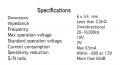
I'd like to record some nature sounds that are much much quieter than 85db, and there is obviously a noise floor with these tiny electret mics. Looking at the specs from these mics how do I figure out the noise floor?
If I wanted to go shopping for an electret with a low noise floor, is there a way to tell how each one compares to others when it comes to the noise floor?
I just measured the output from my amp circuit -22db in a quiet room. And -55db with the electret capsule shorted. So the pre-amp is pretty quiet.
There it is (I think) Measured at 1 Pa or 92 db minus 65 db s/n leaves 27 db. About like the sound in a bedroom at night.
I'm not sure you will find much better because most of the noise is the little amplifier inside the microphone. You might be able to swap it out with a better one I suppose.
This might be useful. http://www.analog.com/library/analo...-05/understanding_microphone_sensitivity.html
I custom built a stereo microphone from arrays of 5 mic capsules in parallel at each channel. Such an array assembly helps to dramatically raise the S/N ratio: the audio signals from the capsules add up because of their synchronicity while the noise from the individual capsules (which is stochastic) tends to cancel out. The mics I used had a sensitivity of -58dB (IIRC), the best I could get at this size and at a reasonable cost at that time. I estimated that the sensitivity of the whole assembly (microphone array and dish) is comparable to that of a human ear. Not bad!
It probably isn't even close to being like a human ear, which can adjust down to 0 db I think. But does this practice of paralleling mics work in theory and practice?
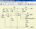
#12, so you like my idea of turning R4 into a pot and VR1 into a fixed resistor? What about my theory about noise at very high gain? Would a 1K pot be realistically quieter at the R4 position, than a 500K pot at VR1?
Do you really need a gain of 228?
Even if you do, I would see about reducing the impedance of that feedback loop.
If you're looking at an input voltage peak of 17.5 millivolts peak to hit the 9 volt rail, that is all the voltage that will be applied to the grounding resistor in the feedback loop. The TL-071 can easily drive 1 ma, so that suggests a resistor of 18 ohms to ground and a feedback resistor of 4k. See where I'm going here?
The cost will be in the size of C2. If it has to pass 40 Hz at 18 ohms (math math math) that's 220 uf. Not so bad in a world where you can get 220 uf for 15 cents.
These ideas suggest that some very reasonable values can be had here, like a 100 ohms to ground in series with a 1k pot and a 22k feedback resistor.