amp volume control

Thread Starter

Prince Imhotep

Joined Feb 9, 2014
13
Hi,

I'm building an audio power amplifier using this chip http://www.st.com/web/catalog/sense_power/FM125/CL1503/SC979/PF65141?referrer=70071840 ,
TDA7264 25 W + 25 W stereo amplifier with mute and standby.

Schematic:


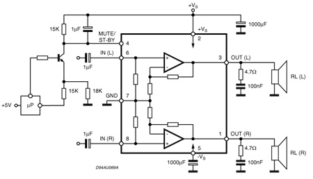
I'm building the same circuit shown in the applications section of the datasheet, with the addition of a B250K double potentiometer on the audio input terminals.


The only problem is the potentiometer isn't linear in controlling the signal, it starts at mute, then when I move the slider the sound steps up suddenly, then stays constant, then begin to increase gradually. I wanted to make a buffer circuit around the potentiometer to assist in making it more linear, so any suggestions.

Also if you have other ideas in mind about controlling the volume in a better way or any other ideas about the circuit itself, be my guest.

All suggestions are appreciated.

Thanks.
 
Last edited:

#12

Joined Nov 30, 2010
18,224
Were you careful to buy audio taper volume controls?

The datasheet does not show any drawings of volume controls, so we wish you would show us a drawing of how YOU connected them.

ps, 100k is usually a more reasonable size and easier to purchase. Sometimes the value is as low as 10k each.
 

Thread Starter

Prince Imhotep

Joined Feb 9, 2014
13
I didn't include a schematic and a photo of the pot at the beginning, my bad. I edited the post, I hope it's more clear.

My addition isn't that radical actually, the outer terminals of the pot -that is for each internal slider- one connected to the audio source wire, the other is connected to the ground/common, and the middle terminal is connected to the audio input terminal of the chip.
 

Thread Starter

Prince Imhotep

Joined Feb 9, 2014
13
In the picture I included the pot has two sets of three terminals lined on the same brown piece of plastic. the resistance between the outer terminals -that is on the same plastic piece- is constant i.e. 250K, the terminal in the middle is variable to both terminals. If you connected either of the outer terminals, one to the ground/common and the other to the audio source/wire, and the middle terminal to the audio input terminal in the chip, you'll always get a variable control over the volume, and I guess this is the right configuration.
 

#12

Joined Nov 30, 2010
18,224
"B" means wrong type of pots.

"B" means the resistance taper is linear, but humans don't hear in a linear fashion. They hear in a logarithmic fashion. You need, "A" type pots.
 

#12

Joined Nov 30, 2010
18,224
Interesting. That page explains perfectly that "A" and "B" are exactly reversed from U.S.A. to Europe. Is Egypt in Europe? (Don't answer that.)

Take an ohm meter with you so you can be sure the resistance of the pot is 10% from the low volume end and and 90% from the high volume end when the knob is at 50% rotation.
 

AnalogKid

Joined Aug 1, 2013
11,043
Arbitrarily label the three terminals on one wafer as A, B, and C, with B as the center terminal. Adjust the pot to 50% rotation. Measure the resistance from B to A and from B to C. The two reading should be approx. 25K and 225K. For whichever of the two readings is lowest, that outside terminal should conntect to ground in your circuit, and the other outside terminal connects to the audio input. Note, keep the coupling capacitor between the pot wiper and the chip input. Some audio power amp chips have strange input DC characteristics and don't like to be grounded directly.

If you can't find a true log-taper pot in your area, you can convert what you have to a good-enough approximation. Here is an excellent article on pots. About half-way down it gets into how to convert a linear to a log.

ak
 

Thread Starter

Prince Imhotep

Joined Feb 9, 2014
13
Thank you all guys for the help you provided, really appreciate it. For the last few days I've bean occupied so I still didn't get the pot.

#12 the document you attached is fascinating, but I think I'll stick with a regular positive log pot, to keep the full resistance value which I guess is necessary.

Adjust the pot to 50% rotation. Measure the resistance from B to A and from B to C. The two reading should be approx. 25K and 225K. For whichever of the two readings is lowest, that outside terminal should conntect to ground in your circuit, and the other outside terminal connects to the audio input.
Thank you AnalogKid, I'll keep your advice in mind.

Note, keep the coupling capacitor between the pot wiper and the chip input. Some audio power amp chips have strange input DC characteristics and don't like to be grounded directly.
It happens that my circuit is arranged the same way for the same premonition. I didn't know how the IC will "behave" if both it's input "legs" were connected to the common/ground terminal, so I kept the coupling caps in between.

There is this thread I found, phase fired controller cuircuits/devices help that is asking about controlling the volume by directly controlling the source power using Triacs or Thyristors, I think he's using a single power source. The IC used in there is the same model as mine, so I thought I might ask if that was possible?
 
Last edited:

GopherT

Joined Nov 23, 2012
8,009
We still haven't seen your circuit. Normally the volume control is at the input of a power amplifier like yours. Also, if connected correctly, the input would be essentially shorted to ground when volume is all the way down so we need to make sure you are connecting it correctly.

It should be to the left of the input caps on your circuit drawing. That way the cap protects any input bias on the chip. When looking at the knob with pins at the bottom, your audio signal should go into the left legs, out the center (wiper) leg and the right leg connected to ground.

Cheers and stay safe at the square.

Also, you can google some tricks to convert a linear potentiometer to behave like a psudo-log potentiometer. For instance, on a 250k ohm pot, add a 1M ohm resistor from each outside pin to the inside pin.
 

Thread Starter

Prince Imhotep

Joined Feb 9, 2014
13
We still haven't seen your circuit.
My circuit is divided into two parts, the power part, and the amplifier part. the amplifier part is almost exactly as the one described by the schematic on my first post. The only difference between my circuit and the schematic, is the volume control pot.

Normally the volume control is at the input of a power amplifier like yours. Also, if connected correctly, the input would be essentially shorted to ground when volume is all the way down so we need to make sure you are connecting it correctly.

It should be to the left of the input caps on your circuit drawing. That way the cap protects any input bias on the chip. When looking at the knob with pins at the bottom, your audio signal should go into the left legs, out the center (wiper) leg and the right leg connected to ground.
And your description of how it should be connected matches exactly the way I connected it.

The power part is a simple transformer/bridge rectifier like this one, in addition to a 2200uF/50v cap to smooth things:


The transformer ratings are 230v/35v at 3A.

The question I posted in my former post is, can I control the volume by controlling the power circuit using Triacs or Thyristors?
 

#12

Joined Nov 30, 2010
18,224
No. Lowering the supply voltage does not turn the gain down. It just makes the amplifier start clipping the output.
 
Top