A working Sprectrum Analyzer schematic????

Thread Starter

dyeraaron

Joined Oct 27, 2008
57
Hey guys,

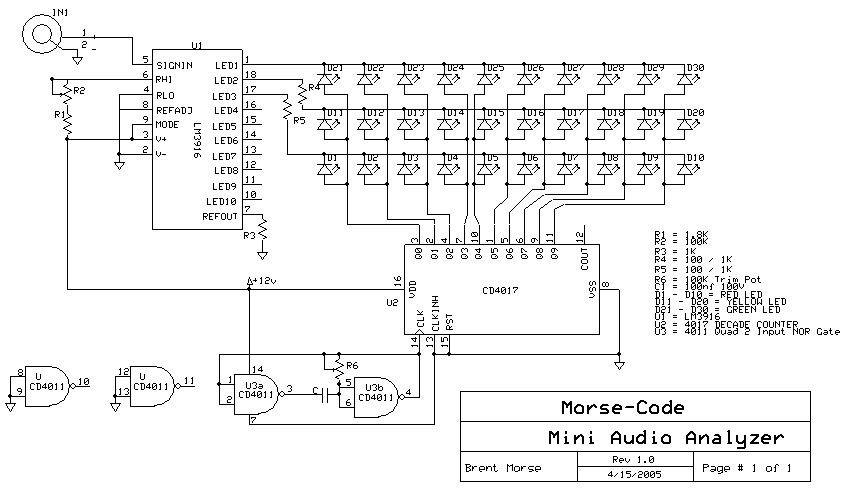
I'm going into my final 2 classes for my degree @ ITT in electronic Engineering. I wanted to build two things for my capstone...a Thermostat and then an LED or Bar Graph LED spectrum Analyzer...Now I've seen all the You tube videos where people post there analyzer up and they look great...problem is I can't ever see any schematics.....I'm just trying to find something with an LM3915 and a few 741 op Amps for my filters and maybe a 4 x 10 or 5 x 10 rows of LEDS. Please help...any input is deeply appreciated.
 

BMorse

Joined Sep 26, 2009
2,675
Have you actually built that circuit? Doesn't look right to me for a spectrum analyzer. Where are the filters?

The LM3916 is a monolithic integrated circuit that senses analog voltage levels and drives 10 LEDs, providing an electronic version of the popular VU meter. A single pin changes the display from a moving dot to a bar graph. The circuit contains its own adjustable reference and accurate 10-step voltage divider. The buffer drives 10 individual comparators referenced to the precision divider. Versatility was designed into the LM3916 so that controller, visual alarm, and expanded scale functions are easily added on to the display system. The circuit can drive LEDs of many colors, or low-current incandescent lamps. Many LM3916s can be chained to form displays of 20 to over 100 segments. Both ends of the voltage divider are externally available so that 2 drivers can be made into a zero-center meter.
Filters for what?? The LM3916 does all the filtering/decoding of one signal...... And yes I have built it before, and it works quite nicely.....
 
Last edited:

BMorse

Joined Sep 26, 2009
2,675
here is a link to a kit for such a device based on the LM3916 Audio VU Meter IC.... reasonably priced I might say...... >> http://www.vakits.com/index.php?cPath=169

I might acquire some for x-mas presents for some of my employees, so they can practice some soldering skills and circuit assembly (These guys can spin a wrench just as good as anybody, but have them solder an LED to a PCB, and you might be in for a surprise!!).......

My .02
 

rogs

Joined Aug 28, 2009
279
Doesn't look right to me for a spectrum analyzer. Where are the filters?
That was my reaction too! I seemed to remember that there was more to a spectrum analyser than a VU meter driver. Band pass filters for a start!

This schematic of an old Velleman kit:
http://www.animeguru.com/images/velleman/k4300.html
gives more of an idea. Sadly the A/D is obsolete, so it's not available any more.

Shows the necessary building blocks though.http://www.electro-tech-online.com/...deas-reviews/86387-led-spectrum-analyzer.html
 
Last edited:

BMorse

Joined Sep 26, 2009
2,675
ok, If you have Eagle Cad, here is a link to the projects download section (http://www.cadsoftusa.com/cgi-bin/d.../download.htm.en&dir=eagle/userfiles/projects), look for "audio_spectrum_analyzer.zip", and there is a complete project including all the filters....

This is a short description for the project:

It's an audio spectrum analyzer use a led matrix which can display in
resolution of 10 x 10. My project has 10 channels: 32Hz, 64Hz, 125Hz,
250Hz, 500Hz, 1kHz, 2kHz, 4kHz, 8kHz & 16kHz.
It's just a simple project.
On a side note, the OP should be the one asking these questions, I was kind of expecting him to ask that question, and I would have gone on from there and told him about filtering for each frequency notch he wants.... I did not want to do "all the work" for him as we have always suggested the OP should do most of the work and we are here to guide them along the way..... so lets let the op do the asking, then we could direct more of the attention to guiding him as he does his school work....

My .02
 
Last edited:

Thread Starter

dyeraaron

Joined Oct 27, 2008
57
Morse,

Thanks for the help to begin with.....The last project you had posted...the audio_spectrum_analyzer.zip...I had found this before....I built the 100 LED matrix for my display last night and its looking good so far......I have both LM3915 and LM3914 but I'm going to go with the LM3914. Do you guys have any suggestions on Op amps to use...I have 741s, 386s an LM3900 dual Op amp and LM224 Dual Op amp. I didn't know about the LM3916 though...thats cool.... This may sound like a dumb question..but for the entire circuits input...Would this come from a channel on the stereo where you plug your speakers in...???? I was thinking more like an RCA jack but where could I plug the other male side into?
 

Wendy

Joined Mar 24, 2008
23,421
here you go.....
I don't see it either. Asking question is always allowed by forum rules as I understand them. It keeps us honest (and I include myself in that statement).

I see the scan, I see the bargraph, but I don't see the frequency discrimination? I'm not trying to give hard time, just trying to learn something new.
 

BMorse

Joined Sep 26, 2009
2,675
I don't see it either. Asking question is always allowed by forum rules as I understand them. It keeps us honest (and I include myself in that statement).

I see the scan, I see the bargraph, but I don't see the frequency discrimination? I'm not trying to give hard time, just trying to learn something new.

This was just a starting point for him to add filters to discriminate the different frequencies......
 

Audioguru

Joined Dec 20, 2007
11,248
Do you guys have any suggestions on Op amps to use...I have 741s, 386s an LM3900 dual Op amp and LM224 Dual Op amp.
The 741 is 42 years old and has a max output at 9kHz.
The LM386 is a power amplifier, not an opamp. It has built-in negative feedback.
The obsolete LM3900 had four very odd opamps.
The LM224 quad opamp has a max output at about 2kHz.

Use TL071 single, TL072 dual or TL074 quad low noise wide bandwidth inexpensive audio opamps.
 

BMorse

Joined Sep 26, 2009
2,675
I can't figure out what your original circuits function is?

go here, look at the kit and ask them why they call this kit and ask them why they say it is an "Audio Spectrum Analyzer" http://www.vakits.com/index.php?cPath=169

With these parts, you can make numerous circuits such as Battery Monitors, Audio Spectrum Analyzers, and many more.
when I built this particular circuit, I had 7 circuits connected to a 7 band equalizer (Thus turning it into a 7 Band GRAPHIC equalizer), so the input was coming off of each band..... so the input DOES need filtering for the different frequencies.....

My .02
 

Thread Starter

dyeraaron

Joined Oct 27, 2008
57
Thanks for the help guys.....Like I said...my matrix is complete and I'm going to start on my bandpass filters soon (10 of them) I'm thinking of using what a schematic I have says to use in the TL084 op amp.... one last thing....the input signal going to the bandpass circuitry....does this come from a output channel port of a stereo or tv...etc. ???????
 

BMorse

Joined Sep 26, 2009
2,675
Thanks for the help guys.....Like I said...my matrix is complete and I'm going to start on my bandpass filters soon (10 of them) I'm thinking of using what a schematic I have says to use in the TL084 op amp.... one last thing....the input signal going to the bandpass circuitry....does this come from a output channel port of a stereo or tv...etc. ???????

That would connect to the line out or speaker level connections......
 
Top