circuit diagram to breadboard

Thread Starter

mauvehead

Joined Jan 22, 2008
6
Hey all,

This is my first post here. I've just begun my adventure into electronics and I'm still working on the basics. For now I'm working with just understanding the basics of circuits, such as resistors, caps, pots, breadboard, icus, etc..

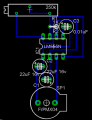
After finding a 555 timer info page, I started trying to design a circuit based on their diagram:


My biggest difficulty is understanding how this translates to a breadboard.

What does the extra line wrapping back into the middle of the 250k pot mean?
What exactly is it saying about pins 1, 2 & 6?
I assume pin 1 goes to ground. But is that some how linked back to pins 2&6? Or is it simply saying, link pins 2&6 and then run that into the positive side of a 22uf resistor that has it's negative side linked to ground?

How can I better understand how to read a circuit diagram and than build it on a breadboard?

Sorry for what must be a horribly simple beginners question. But I haven't found much resources on the actual translation.

Thanks.
 

SgtWookie

Joined Jul 17, 2007
22,230
The "extra line" wrapping back into the middle of the 250K pot is the "wiper" of the potentiometer; usually the middle terminal on a pot. In this schematic, both one end of the pot and the wiper arm are connected to +9v, the other pot terminal is connected to pin 7 of the 555 IC.

Pin 1 is connected to "power supply return". A green dot is not a typical representation of a ground; it's normally depicted as a triangle, or several horizontal lines in a triangular pattern.

Pins 2 and 6 are connected together electrically. There is a 1K Ohm resistor connected between pins 6 and 7, and a 22uF 16V capacitor connected between pin 6 and the power supply return, the + side of the capacitor being on pin 6.

Going through the tutorials on this site will help you to better recognize various schematic symbols.
 

Thread Starter

mauvehead

Joined Jan 22, 2008
6
It's not so much the symbols as figuring out how to layout on a breadboard what I see in a diagram. I'm aware of the symbol for ground but mistakingly assumed that was an alternative.. I guess I just haven't seen that VS ground..
 

SgtWookie

Joined Jul 17, 2007
22,230
Oh, OK.

Well, IC's have either a dot or a notch on one end. With that dot/notch to the left, looking down at the top, start counting from the lower left pin, which is 1, towards the right, then when you get to the end, jump to the top and count left.

A 555 IC might look sort of like:
Rich (BB code):
  8 7 6 5
_|_|_|_|_
)        |
-|-|-|-|-
 1 2 3 4
Electrolytic capacitors usually have a lead that is shorter than the other, with an arrow or mark pointing to it showing that it is the negative (-) lead.

Do you have a part number for your breadboard, or a picture of it?

Usually, you plug an IC into a breadboards' holes so that it's leads are straddling a groove. On either side of the groove, there is normally a series of 5 holes in a line that are all connected together. With the IC plugged in, that leaves you 4 holes to plug in components or wire leads. Don't try to force large wires in the holes, as you'll damage the breadboard.
 

SgtWookie

Joined Jul 17, 2007
22,230
Well, John Luciani and I were talking about two different kinds of "breadboarding".

The kind I was talking about are generally made from a white plastic, with lots of rectangular holes for wires/component leads, and are made to be reused. Please see the attached image for more information.

The kind John is talking about is more like "stripboard" or "perfboard"; fiberboard that has pre-drilled holes in a 0.1" square pattern, and may or may not have "pads" or copper on the other side.

In the example image attached to this post, the "bus strip" is for power and ground connections. Normally, you would use one bus for Vcc (or the + voltage from your supply) and the other for ground (or power return.) The "socket strip" is where you would plug in IC's, wires and discrete components like capacitors, resistors, inductors, etc. Jumpers and/or components are placed between the "socket strip" and "bus strip" as needed.
 

Attachments

SgtWookie

Joined Jul 17, 2007
22,230
OK, attached is a sample board layout of your circuit; something that's in between how a breadboard might look and how an actual PCB might be laid out; obviously leaning towards the former. It's just kind of thrown together, but you can see how the connections need to go. Power and ground connections aren't shown.

C3 isn't in your original schematic, but it's important to have a small capacitor on that pin if it's unused, to keep it from aimlessly floating around and changing your timer's parameters.
 

Attachments

mik3ca

Joined Feb 11, 2007
189
that yellow box with 250K in it and the arrow pointing to it is a potentiometer.

basically it is just the same as a resistor (like another rectangular box with two black lines coming out of it), except that with a potentiometer, there are three connection points.

the middle point is the wiper. If you only use the two end points, then you made a resistor, and the value of it is the value marked on the potentiometer.

So to make the yellow box resistor, on the top left of the diagram, pick two pins on your potentiometer that are next to each other, and connect them together any way you like. The connected pins now go to the point where the +ve side of the battery connects. The remaining potentiometer connects to the 1K resistor.
 

Thread Starter

mauvehead

Joined Jan 22, 2008
6
SgtWookie, on that image shouldn't Pin 1 be the bottom left corner of the 555? If so, why is it running to C2? Shouldn't it be going to ground/power-supply-return? Also, it shows that wire running out the bottom (right hand side) of the 555 into C3.. What in the world? I'm even more confused now. Also it shows C1 and C2 linked via their negative pin? Why?
 

SgtWookie

Joined Jul 17, 2007
22,230
Yes, you are correct - pin 1 is in the lower left corner, and it should be connected to ground.

I mentioned that connections to power and ground were not shown, but you're questioning the image and that shows that you are thinking. :)

C2 needs a reference from where to accumulate a charge potential from. C1 and C2 are referenced to pin 1 as well, as pin 1 is ground. Everything in electronics needs a reference point, and we attempt to maintain sanity by declaring at least ONE point in a given circuit to be at an electrical potential of ZERO VOLTS, or ground.

Why not go through some of the tutorials on this site? You'll learn a lot, and it'll be much easier to understand all of this stuff after you've gone through them.

It'll be fun, I promise ;)

I've attached a schematic I threw together in a few minutes of what you posted originally which was the basis for the layout that you posted in the beginning. It's not pretty, but pretty wasn't my goal; it was just to get the layout - but now you've called my hand. :eek: Ugly as it may be, it's another interpretation/adaptation of your original schematic, posted with all of it's warts.
 

Attachments

Thread Starter

mauvehead

Joined Jan 22, 2008
6
Thank you so much for taking this time to (re)explain things (over and over) to me. I've been doing my best to read the allaboutcircuits website and am about 3 or 4 chapters into the first Volume. You suggest I do some of the tutorials, would those be on http://www.allaboutcircuits.com/vol_6/index.html or at another location? Also, what software are you using to generate those schematics?

I thank you again for your patience and hope in the future we can have more interesting conversations as I learn more.
 
Top