Facebook
 Google
 GitHub
 Linkedin
O.K. Guys/Gals...
I have a mobility scooter that is acting up pretty darn good these days.
NOTE: No longer under warranty and Medicare will not pay for it.
The problem was this:
A) Intermittent(...no, don't say that!)
B) When it does not work:
When pressing the forward/reverse accelerator pot the motor
tries to go forward, but may only creep or not go at all.
I have since took a lot of variables out of the equation:
1) The "forward/reverse accelerator pot"
2) The "max speed pot"
3) The circuit board with the pot connectors
4) The cable wiring from the pots to the motor controller
5) The wires from the motor controller to the batteries
6) The wires from the motor controller to the Motor
I've pretty much narrowed it down to the motor controller
The catch: A new replacement motor controller for this
scooter runs in the neighborhood of $500 - $600 US.
That is a big ouch!
I even when into the motor controller and replaced the 3 24V
relays and ended up with the same symptoms.
Thus I am here in hopes for some suggestions and or ideas on
my next step.
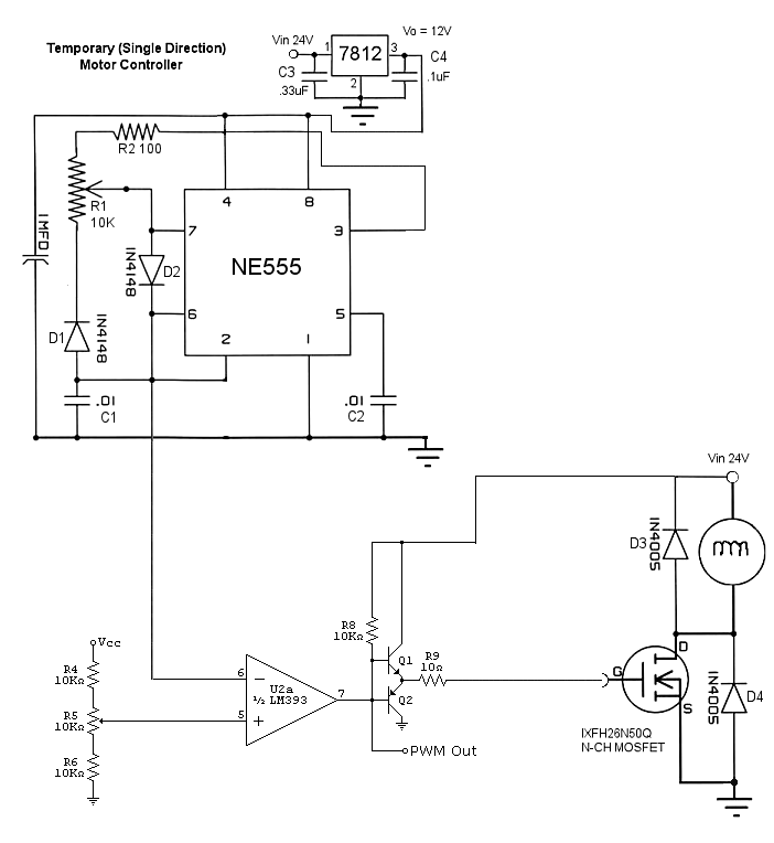
My inclination is to build a new controller.
Meanwhile I thought of just building a very basic controller that will
enable forward movement only.
Haven't really done any testing in the motor itself other than running it from
a 24V bench power supply.
...more to come
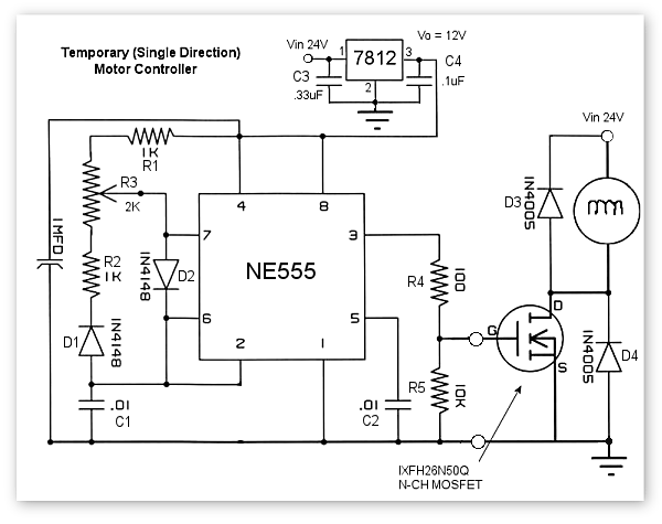
Notes on this circuit:
1) D4 is not needed as the MOSFET has an internal diode
2) I need to verify the appropriateness of R3 (2K pot)
Changed from 2K to 500K(V Gate increased from 7.94V to 10.54V at full on pot)
3) I need to verify the pot is configured in the circuit correctly
Pot was incorrectly configured, fixed this.
4) I need to record the Gate voltage and make sure it is bringing
the MOSFET into saturation.
Not sure what nomenclature designates this in the datasheet.
MOSFET Datasheet
Problems with it thusfar...
With 24V bench supply or 24V Battery, the wheels spin and the speed varries while on a block but do not when on ground.
Not sure why that is.
...After making changes (In Dark Red, above) The wheels spin faster, but when on the ground, the scooter does not
move. What would I check from a motor perspective?
Still not sure the MOSFET is operating correctly. Should not the 555 pulses to the gate always be at full on Voltage, like 10V? It should not vary from 0V - 10.5V!?
I have a mobility scooter that is acting up pretty darn good these days.
NOTE: No longer under warranty and Medicare will not pay for it.
The problem was this:
A) Intermittent(...no, don't say that!)
B) When it does not work:
When pressing the forward/reverse accelerator pot the motor
tries to go forward, but may only creep or not go at all.
I have since took a lot of variables out of the equation:
1) The "forward/reverse accelerator pot"
2) The "max speed pot"
3) The circuit board with the pot connectors
4) The cable wiring from the pots to the motor controller
5) The wires from the motor controller to the batteries
6) The wires from the motor controller to the Motor
I've pretty much narrowed it down to the motor controller
The catch: A new replacement motor controller for this
scooter runs in the neighborhood of $500 - $600 US.
That is a big ouch!
I even when into the motor controller and replaced the 3 24V
relays and ended up with the same symptoms.
Thus I am here in hopes for some suggestions and or ideas on
my next step.
My inclination is to build a new controller.
Meanwhile I thought of just building a very basic controller that will
enable forward movement only.
Haven't really done any testing in the motor itself other than running it from
a 24V bench power supply.
...more to come
Notes on this circuit:
1) D4 is not needed as the MOSFET has an internal diode
2) I need to verify the appropriateness of R3 (2K pot)
Changed from 2K to 500K(V Gate increased from 7.94V to 10.54V at full on pot)
3) I need to verify the pot is configured in the circuit correctly
Pot was incorrectly configured, fixed this.
4) I need to record the Gate voltage and make sure it is bringing
the MOSFET into saturation.
Not sure what nomenclature designates this in the datasheet.
MOSFET Datasheet
Problems with it thusfar...
With 24V bench supply or 24V Battery, the wheels spin and the speed varries while on a block but do not when on ground.
Not sure why that is.
...After making changes (In Dark Red, above) The wheels spin faster, but when on the ground, the scooter does not
move. What would I check from a motor perspective?
Still not sure the MOSFET is operating correctly. Should not the 555 pulses to the gate always be at full on Voltage, like 10V? It should not vary from 0V - 10.5V!?
Last edited:
")