Facebook
 Google
 GitHub
 Linkedin
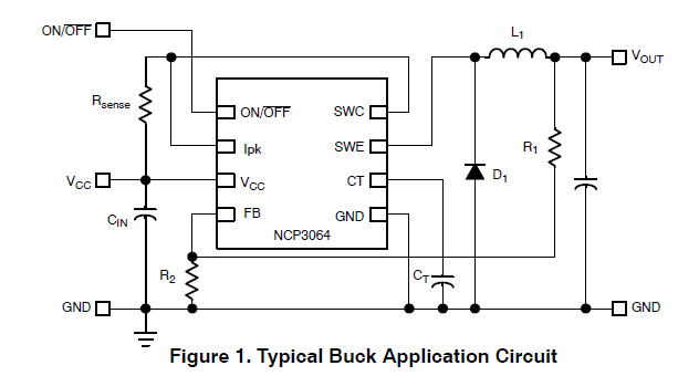
I have tried and tried to find the answer to this myself, but I submit to defeat. I'm working with a DC/DC Step-up/Down/Inverting Switching Regulator, the NCP3064 in a step-up configuration. My goal is a voltage input of ~11 to 14V DC with an output of 19.2V at 350mA (can be over 19.2V but not under).
There is a very handy design tool for the NCP3064 which is an Excel spreadsheet that does calculations for you, found HERE. In this design tool under the "Boost" tab, Section 3 specifies Set ΔIL/IL(avg), then it specifies "it is suggested that ΔIL be chosen to be less than 10% of the average inductor current, IL(avg)."
I am quite confused on this point. What is ΔIL? and where can it be found on a datasheet for an inductor? I have looked at a number of inductor spreadsheets in an effort to find these values (ΔIL and IL(avg)). I have found Idc (DC Current) and Isat (saturation current), as well as Irms which I'm not sure what that means exactly, I think it's root mean square current.
Biggest problem I'm having is how to determine the ripple current of a given inductor? Perhaps the ΔIL/IL(avg) is just the tolerance of the inductor?