Capacitors on Current Source

Thread Starter

jbord39

Joined Mar 31, 2010
41
Hey guys,

I am building a current source for driving a laser diode from 0-2A. Here is the circuit I am using currently:


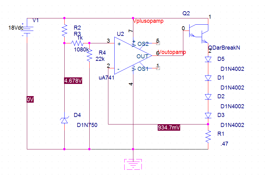
The 1080kOhm is actually 80kOhm with a 1Meg potentiometer, used for varying current output.

My question is where should I put capacitors to increase its stability? Also would zener diodes across the laser diode protect it from current spikes? I have burned out a diode already and they are $50 bucks so any help on making this regulated is appreciated.

Thanks,

John
 

SgtWookie

Joined Jul 17, 2007
22,230
Why are you using a Zener diode instead of a precision voltage reference?

Why are you using a 741 opamp instead of a more modern one? It won't work as shown, because a 741 opamp cannot see that close to the negative rail. You'll fry the output transistor and your laser diode to a crisp. Didn't we go through this already?

Do you have 0.1uF and 1.0uF caps across the opamps' power pins?
 

Thread Starter

jbord39

Joined Mar 31, 2010
41
I am using the LM358, I just forgot to change the schematic. The circuit is working now. I also used a Zener to set the reference voltage because the specific amount of current doesn't really matter, and the Vzk reverse breakdown is pretty consistent (I just need the current to not possibly spike). I don't have caps there but will add them.

What about some sort of failsafe around the diode. Is this possible?

Thanks,

John
 

SgtWookie

Joined Jul 17, 2007
22,230
The LM358 is a dual opamp; pretty old one, too.

Did you wire the unused channel as a voltage follower with the noninverting input tied to ground? If you don't, it may oscillate unpredictably and affect the channel you're using.

A 5.6v Zener is more stable over temperature than other voltages; that's just how it works out. You seem to be using a 4.6v Zener. But if you really want to keep the current stable, you'll get a precision reference and stop fiddling around with Zeners. You'll also get a better opamp that has zero drift.

Don't bother with a Zener at the output, as that won't work.

If you were serious about protecting your laser, you'd use better components.
 

Thread Starter

jbord39

Joined Mar 31, 2010
41
Yes I have the unused portion wired like that. The Zener diode used in the schematic is not the exact one I am using, mine is 5.1V. I am curious why the Zener diode is less reliable than a precision voltage reference in this case. The current is going to be constantly changed so a precise value is not necessary; even a 1V change in Zener voltage (which is unlikely since Vzk is mostly a function of temperature and it is well below its wattage rating) would result in only 10% more current through the diode at it's maximum setting. The Zeners breakdown voltage is also a function of doping concentration so I don't know any reason that one Zener is more reliable than the other.

I have tested the circuit and it seems to work well. I am wondering how to add a laser diode failsafe.

Why would a Zener in parallel with the laser diode (and maybe a regular diode reversed to prevent negative voltage not work?

Thanks,

John
 

kubeek

Joined Sep 20, 2005
5,794
The zener won´t work because it will allways have a bit higher voltage than the laser diode, so the most current will still flow through the laser. You could add a 3A fast-blow fuse in series with the laser. I am pretty sure the laser has more specs than just the current and forward drop, so why don´t you share the datasheet with us?

5.1V diode has the lowest temperature coeficient than the others.
Precision voltage reference is better just because it is precision. It is deigned to stay the same over wider range of voltage and temperature.

Like I said in the first of your at least three threads, you should have a failsafe resistor from the viper of the pot to ground just in case the viper looses contact. Also try to stick with the original thread so everyone can know what is going on.

To make this circuit more reliable, you should thoroughly check it with a dummy load over wide range of voltages to see for example how the opamp behaves with too low supply voltage. Also a lot oversized transistor will add to reliability. Using higher value for the base resistor, so that when the opamp outputs 0v the transistor just passes a little over 2A could work too.

For overvoltage, a slow-blow fuse and MOV crowbar on the input.
 
Last edited:

kubeek

Joined Sep 20, 2005
5,794
The cap you were asking is like allways the decoupling cap. 100nF directly across the opamp´s supply pins.
BTW do you have an oscilloscope? You should check how your PSU behaves under load.
 

wayneh

Joined Sep 9, 2010
17,496
You could add a 3A fast-blow fuse in series with the laser.
+1
An excellent (cheap, effective, simple) failsafe approach, no matter what else you do. You might also consider a low pass filter to take out any spike that might be faster than the fuse.
 

SgtWookie

Joined Jul 17, 2007
22,230
One item you really need to do is to update your schematic to your circuits' current configuration.
Split the 1080k resistor into a separate pot and 80k Ohm resistor; however, 80k is not a standard value of resistance - it's probably 82k.
Replace the 741 opamp with an LM358.
Document in the schematic that D1, D2, D3 and D5 actually represent a single laser diode that has a Vf of ____ at the rated current of _____, maximum If is ______.
Document what the part number of the Darlington transistor is.

The more accurate your schematic is, the better quality of answers you will get.

If you don't expend the effort to accurately document your circuit in a schematic, people will likely take you as not very serious about your project.
 

Thread Starter

jbord39

Joined Mar 31, 2010
41
I am pretty sure the laser has more specs than just the current and forward drop, so why don´t you share the datasheet with us?
I have had a very hard time finding a datasheet on this diode. It is the A140 445nm diode. They are harvested from Casio DLP projectors, and have a current rating from 0 to around 2 Amps. People have posted going higher but I would like to be safe.

Like I said in the first of your at least three threads, you should have a failsafe resistor from the viper of the pot to ground just in case the viper looses contact. Also try to stick with the original thread so everyone can know what is going on.
Didn't mean to create so many topics, sorry. I am confused how the potentiometer losing contact could be a problem though, since even if the potentiometer's resistance was 0 Ohms, this would still apply only 1V to the .47Ohm resistor which would be about 2A. If the potentiometer started floating then the V+ terminal would be at 0V which would put zero current through the driver.

To make this circuit more reliable, you should thoroughly check it with a dummy load over wide range of voltages to see for example how the opamp behaves with too low supply voltage. For overvoltage, a slow-blow fuse and MOV crowbar on the input.
Thanks, I will get a slowblow fuse. What is a MOV crowbar?
 

Thread Starter

jbord39

Joined Mar 31, 2010
41
+1
An excellent (cheap, effective, simple) failsafe approach, no matter what else you do. You might also consider a low pass filter to take out any spike that might be faster than the fuse.
I will do this, thanks. Would the lowpass filter go between the power supply and the collector of the darlington?
 

Thread Starter

jbord39

Joined Mar 31, 2010
41
The cap you were asking is like allways the decoupling cap. 100nF directly across the opamp´s supply pins.
BTW do you have an oscilloscope? You should check how your PSU behaves under load.
I do have an oscilloscope. I will update with pictures of the voltage across the .47Ohm resistor later.

One item you really need to do is to update your schematic to your circuits' current configuration.
Here it is, thanks for your patience.


I am using the 2n2222a followed by the tip3055 because at TIP-120 was giving me too much gain. The slew rate of the op-amp couldn't keep up with the gain of the transistor and it oscillated from it's set point by +/-300mA.

Thanks,

John
 

SgtWookie

Joined Jul 17, 2007
22,230
Is R1 a wire wound power resistor, by any chance?
Most of those are not good to use for current sensing, as they have some inductance to them - unless they're specifically stated to be non-inductive; non-inductive wire wound resistors are available.

Consider placing a capacitor from the opamps' noninverting input to ground. This will keep the reference voltage more stable, and will also effect a "soft start" for the laser current.

One technique I've seen used for laser supplies is to have a comparator trip an SCR to "crowbar" the supply output if a threshold current is exceeded. The SCR stays conducting, shunting the supply current to ground until the power is turned off.
 

Thread Starter

jbord39

Joined Mar 31, 2010
41
Is R1 a wire wound power resistor, by any chance?
Most of those are not good to use for current sensing, as they have some inductance to them - unless they're specifically stated to be non-inductive; non-inductive wire wound resistors are available.

Consider placing a capacitor from the opamps' noninverting input to ground. This will keep the reference voltage more stable, and will also effect a "soft start" for the laser current.

One technique I've seen used for laser supplies is to have a comparator trip an SCR to "crowbar" the supply output if a threshold current is exceeded. The SCR stays conducting, shunting the supply current to ground until the power is turned off.
The wirewound resistor is noninductive. What size capacitor would you recommend to put on the noninverting input, .1uF?

I have also never used an SCR before. What model would you recommend for this sort of thing.

Here are the pictures from my oscilloscope of the voltage across the .47ohm resistor, where channel two (blue) is at ground:
at 500mA

at 1A:


and at 2A:


Thanks,

John
 

John P

Joined Oct 14, 2008
2,025
Your LM358 is showing its roots as an LM324: the power pins are numbered as if it were a 14-pin package. That (both parts) is a slow old amplifier, so if speed is an issue, as it apparently is, you could maybe solve it by switching to a faster amp.

If the other amp in the LM358 package isn't used somewhere else that your diagram doesn't show, it should be set up to do something that keeps the package stable without wasting power. I'd tie the positive input to Gnd, and the negative input to the output. That makes a voltage follower delivering zero volts--not very useful most of the time. And, it's best to put a filter capacitor (0.1uF maybe) on the op amp's power supply, between pin 4 and pin 8, as close to the pins as you can get it. These things all help make an op amp work reliably.
 

SgtWookie

Joined Jul 17, 2007
22,230
The wirewound resistor is noninductive.
OK, good.

What size capacitor would you recommend to put on the noninverting input, .1uF?
That's a good value.

I have also never used an SCR before. What model would you recommend for this sort of thing.
Let's skip the SCR idea for now.

You can decrease the required response time from your opamp/Darlington by placing a cap across your laser; this will help a great deal to make transients a minor event. Try it in simulation using a value of 100uF to 1,000uF. Transients are immediately coupled through the capacitor to the 0.47 Ohm sense resistor causing the opamp/Darlington to adjust current flow, but the actual current flow through the laser diode will be affected only slightly. Try it in simulation and compare with/without the added cap.
 

Thread Starter

jbord39

Joined Mar 31, 2010
41
Hey guys,

I tried simulating the circuit with a capacitor in parallel with the diode load. If I used a capacitor below 1000uF it seems to oscillate around the set point (although it averages out to the correct value haha). Bigger than that seems to be alright.

-John
 

SgtWookie

Joined Jul 17, 2007
22,230
Were you looking at the current through the diode string, or the voltage on the sense resistor?

The important thing is the current flow through the diodes.
 

Thread Starter

jbord39

Joined Mar 31, 2010
41
Yeah, I measured it through the resistor and capacitor. With a capacitor size < 500uF then the output of the diode oscillates like crazy while the current through the resistor is also oscillating. At around 500uF the current through the diode calms down and it is just oscillating through the resistor.

Thanks,

John
 
Top