![]() |
|
|||||||
| The Projects Forum Working on an electronics project and would like some suggestions, help or critiques? If you would like to comment or assist others with their projects, this is the place to do it. |
|
|
|
Thread Tools | Display Modes |
|
#1
|
|||
|
|||
|
I am about as new to electronics as you can be. So bear with me.
I am trying to do a very simple LED circuit for a nightlight, using a Photocell to turn it on at night and off in the daylight. I found the circuit on the instructables forum and want something VERY simple. I do not care if it goes on when it is dim in the room, or when it is cloudy (i want some differentiation, but I am not picky). THe instructables I looked at is here: http://www.instructables.com/id/Blue...tic-LED-light/ I got the same parts he lists: 9 Volt Battery Photo-Cell NPN Transistor (2N 4401) Super Bright White LED 100K ohms Resistor 470 ohms Resistor 9 Volt battery Snap Except I want to run this of of a Wall Wart, and have been using a 12volt source on my breadboard. 
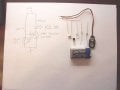
I wire it up to match his breadboarding and it does not work. The LED comes on, but the Photo Cell does nothing to effect it. I have tried 2 different photocells that i got from All Electronics (smaller physically than his) and I get nothing. I am trying to figure out whether i am messing up the breadboard work, or the wrong photocells. Here are some Pics. I apologize, they could be sharper, but they show the circuit: ![]() ![]() ![]() The fullsize images are here: http://www.jklinephd.com/photoled1.jpg http://www.jklinephd.com/photoled2.jpg http://www.jklinephd.com/photoled3.jpg The photocells came from jameco and here are the stats: PHOTOCELL,90mW,150V PEAK, 27KohmMAX LIGHT,2MohmMIN DARK Jameco#:120310 PHOTOCELL,90mW,150VPK,5Kohm, MAX LITE,20Mohm MIN DARK Jameco#:202391 PHOTOCELL,150mW,200VPK,3.6Kohm MAX LITE,0.3Mohm MIN DARK Jameco#:202438 Suggestions? Errors I have made? Thanks Jeff |
|
#2
|
|||
|
|||
|
When I went to the website you linked,
but I couldn't find the schematic even though they talk about the schematic in step 1. From the parts list and your pictures, I gather that the way that this circuit works is that the 100 kΩ fixed resistor and the light-sensitive resistor are connected as a voltage divider which goes to the base of the transistor. Quote:
Your parts list says 100K ohms Resistor 470 ohms Resistor but, when I look at the colors on the resistors, what I see are 680 Ω and 1000 Ω. Using 680 Ω instead of 470 Ω won't make much of a difference, only make the LED not shine as bright but using 1 kΩ instead of 100 kΩ will completely throw off the voltage divider, explaining why you can't get the thing to shut off. Last edited by rspuzio; 08-31-2009 at 02:14 AM. Reason: explanation |
|
#3
|
|||
|
|||
|
Quote:
I have to say Oops. Going to school does not means you can read. You are correct I have a 1000 Ω Not 100k Ω It is off to RS tomorrow. Attached is the Pic of the Schematic Can you explain why? I think i know, but I need to tune up my understanding. Thanks Again. jeff |
|
#4
|
||||
|
||||
|
It looks like the photo-cell is connected to +12 instead of ground in picture. The 100k supplies base current, thr photo-cell shunts the base to ground, turning off the light. A low ohm sensor should work best, like the 3.6K.
Last edited by Bernard; 08-31-2009 at 04:52 AM. Reason: spelling error-s |
|
#5
|
|||
|
|||
|
Quote:
school of hard knocks seems to be the place for learning that. The good news is that there aren't that many values in common use, so it doesn't take too long before, say, "1000 Ω" pops into your head when you see brown-black-red without even thinking about it. Quote:
to 0.7 volts more positive than the emitter. In your schematic, the photoresistor and the fixed 100 kΩ resistor form a voltage divider so, in order to have the transistor (and hence the LED) turned off, you need to have the voltage across the photoresistor be less than this turn-on voltage. So let's calculate the maximum resistance which will still keep your LED turned off. Letting x be the resistance of the photoresistor, we have which solves to x = 5.25 kΩ. If we look at the specs of the three photoresistors, we see that the third one says 3.6 kΩ when fully lit, so that should turn off once the lights go on. The second says 5 kΩ when fully lit so likely the only way to turn that one off would be to shine a bright light right on the photocell. The first one says 27 kΩ so it has too much resistance to work in this circuit. Also, it's worth noting that you can adjust the light level at which the circuit turns on by changing the resistor from 100 kΩ to some other value. Last edited by rspuzio; 08-31-2009 at 06:18 AM. Reason: minor fixes |
|
#6
|
|||
|
|||
|
Quote:
So if i were to get a 50kΩ then I solve it to 3.2kΩ photocell and a 60 k resisitor would solve to 2.6kΩ. So with a 50k I could use the one photocell marked 3.6kΩ? I could also use a pot with an adjustable resistor amount? Thanks again. Jeff |
|
#7
|
||||
|
||||
|
Just replace the 1k resistor with a 33k or 50k pot. Then adjust the pot until the circuit works at the light level you choose.
|
|
#8
|
|||
|
|||
|
Quote:
Thanks again. THis has been fun and I enjoy learning. I am going though materials and trying to learn the technical side, but sometimes translating technical into practical gets harry. I soldered up the circuit tonight ( I chose a small board, even though I could have just soldered everything together - I have directions), but the Circuit Board (kjust a mock up board from RS) helps me to think it through. I still got the stupid transistor on backwards. UGH. Now I have to get a Solder Sucker to desolder the joints and redo it. Its fun learning. I am going to use a modification of this to light up the eyes of a pumpkin for halloween. Jeff |
|
#9
|
||||
|
||||
|
The minimum beta on 2N4401 is 80. For a collector current of (7V/470Ω) 15mA, you need the base current to be at least 15mA/80≈190uA. This means that, with the photocell completely off, the base resistor needs to be no greater than ≈43kΩ. The photocell ON resistance Rpc(on) must be about
0.5/Rpc(on)<8.5/43kΩ (assumes Vbe(off)=0.5V). Rpc(on)<2.5kΩ. This all assumes you have a fresh battery. Having said that, it may or may not work with the 100k resistor, since most units will have beta>80. |
|
#10
|
|||
|
|||
|
Quote:
[img]http://forum.allaboutcircuits.com/cache.php?url=http://www.photosnag.com/img/4713/n09x0302vnsn/**********[/img] |
|
| Tags |
| led, nightlight, photocell, simple |
Related Site Pages
|
||||
| Section | Title | |||
| Worksheet | Performance-based assessments for semiconductor circuit competencies | |||
Similar Threads
|
||||
| Thread | Thread Starter | Forum | Replies | Last Post |
| Submission, CMOS 555 Long Duration LED Flyback Flasher | Bill_Marsden | Feedback and Suggestions | 43 | 05-03-2010 01:58 PM |
| Pls help me.Need advice | ridge84 | Embedded Systems and Microcontrollers | 4 | 11-29-2009 09:35 PM |
| How to wire up an simple LED with ever changing voltage | princess blacklung | The Projects Forum | 29 | 09-09-2009 01:56 AM |
| LED office-desk lighting system | kdaffolder | The Projects Forum | 1 | 08-04-2009 07:43 AM |
| Math Help with a Simple LED circuit | fish4fun | The Projects Forum | 3 | 03-03-2009 04:04 AM |
| Thread Tools | |
| Display Modes | |
|
|