Facebook
 Google
 GitHub
 Linkedin
Sorry for a lengthy start, but I hope to avoid later explanations. ")
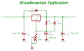
Please take a look at the attached drawing. The problem I'm having is with the linear potentiometer: it's too sensitive for easy adjustment & doesn't have linear sweep. Please read on for more background & what I've done so far.
Background:
Over the past few months I've made a few posts of a PSU in various stages of development. I have received lots of great help from the senior members & moderators. A couple notes from those posts:
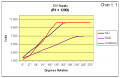
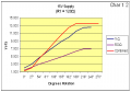
At the moment, I'm working strictly on the positive rail, using either 12V or 15V as the supply. I was under the impression that V\(\small_{IN}\) wouldn't matter so long as it was within the operating range of the 317 specs. But there is some difference in how the range of the pot is affected (i.e., the higher V\(\small_{IN}\) allows a slight increase in range, but essentially the sensitivity up to that point remains unchanged).
WHAT I'VE DONE SO FAR: First, I confirmed the pots are linear type. Next, I researched the problem & found that linear pots aren't always completely linear. I located some sources for adjusting the output of the pot, so if it were graphically represented, it could be made more log or even anti-log. I have tried some of these techniques without positive results. I do not want to limit the range of the pot (Vol VI, Chap 3 stuff) - I simply want a reasonable sweep to V\(\small_{OUT}\), especially (& if doable, lol) for at least 90% of the sweep.
I have tried R1 in ranges from 120Ω to 1kΩ & R2 at 2k, 5k & using Vol VI techniques, some variations of these two. The 2k provides a far better ratio of movement to output in the lower ranges, but still reaches the upper limit well before the stop. With either pot, the last 40%+ of sweep is only adjusting the mV of the upper limit. You can figure the time I've spent messing with the combinations/permutations in adjusting these two variables. Interestingly, I did find the combination of R1=680Ω & R2=2kΩ provided a nice ratio of sweep to output, however, I could no longer swing completely down to 1.2V & the upper limit was capped regardless of the supply V\(\small_{IN}\).
I would prefer to use a single pot on my panel since it's a lot of work to refinish (lol, live & learn - I hadn't anticipated this particular problem since this configuration is so widely used & there are numerous commercial supplies with a single pot for adjustments).
Obviously I'm doing something wrong. Is this fixable by modifying the circuit or adding components or do I need to begin exploring a digital solution?
Please take a look at the attached drawing. The problem I'm having is with the linear potentiometer: it's too sensitive for easy adjustment & doesn't have linear sweep. Please read on for more background & what I've done so far.
Background:
Over the past few months I've made a few posts of a PSU in various stages of development. I have received lots of great help from the senior members & moderators. A couple notes from those posts:
Ron H noted, I would not get full sweep from the 5K pot & he recommended R1 be dropped to 82Ω & R2 changed to 2K (see "What I've Done So Far," below).
eblc1388 & Audioguru noted, R1, often shown as 240Ω in countless 317 references, should be 120Ω instead. After considering their in-put, completing a lot of research, & doing some Ohm's Law calculations (which I posted in that thread), I settled on using a 130Ω resistor in the schematic because mathmatically it made sense to me. (see "What I've Done So Far," below).
beenthere noted, in considering a resistor placed in parallel with R2 to limit the range, that it would have "...a deleterious effect on the adjustment pot." This threw me a bit since basically it was an application from Vol VI, Chap 3 of the AAC guides. But I removed the resistor as he suggested.
About the PSU: This unit is the second part of a two unit set mounted in one enclosure. The other unit is an ATX PSU break-out (which is completed). In the course of working on this project I obtained a rack-mount type enclosure which I gutted for components & re-finished the face to the new applications. I am at the point of building the stand-alone adjustable supply for the unit. As noted in other posts, it is planned as dual rail with selectable current limiting (ranges: 50mA, 100mA, 250mA, 500mA & 1A) & voltage adjustable within the range of the 317/337 ICs. So, no, I haven't made a final decision on the supply voltages. I intend to use an op-amp to simultaniously control the out-put of the rails.
At the moment, I'm working strictly on the positive rail, using either 12V or 15V as the supply. I was under the impression that V\(\small_{IN}\) wouldn't matter so long as it was within the operating range of the 317 specs. But there is some difference in how the range of the pot is affected (i.e., the higher V\(\small_{IN}\) allows a slight increase in range, but essentially the sensitivity up to that point remains unchanged).
WHAT I'VE DONE SO FAR: First, I confirmed the pots are linear type. Next, I researched the problem & found that linear pots aren't always completely linear. I located some sources for adjusting the output of the pot, so if it were graphically represented, it could be made more log or even anti-log. I have tried some of these techniques without positive results. I do not want to limit the range of the pot (Vol VI, Chap 3 stuff) - I simply want a reasonable sweep to V\(\small_{OUT}\), especially (& if doable, lol) for at least 90% of the sweep.
I have tried R1 in ranges from 120Ω to 1kΩ & R2 at 2k, 5k & using Vol VI techniques, some variations of these two. The 2k provides a far better ratio of movement to output in the lower ranges, but still reaches the upper limit well before the stop. With either pot, the last 40%+ of sweep is only adjusting the mV of the upper limit. You can figure the time I've spent messing with the combinations/permutations in adjusting these two variables. Interestingly, I did find the combination of R1=680Ω & R2=2kΩ provided a nice ratio of sweep to output, however, I could no longer swing completely down to 1.2V & the upper limit was capped regardless of the supply V\(\small_{IN}\).
I would prefer to use a single pot on my panel since it's a lot of work to refinish (lol, live & learn - I hadn't anticipated this particular problem since this configuration is so widely used & there are numerous commercial supplies with a single pot for adjustments).
Obviously I'm doing something wrong. Is this fixable by modifying the circuit or adding components or do I need to begin exploring a digital solution?
Attachments
-
 6.1 KB Views: 112
Last edited: