Help with 555 and dimming RGB LED

Thread Starter

Leccy-Lee

Joined Aug 2, 2008
22
Hi, my first post here so please be gentle, i am an Electrical Engineer but Electronics have never been my strong point, although i trying to improve that.

I have some RGB 3-colour LEDs (low-power), 4pin with Common-Cathode and i am trying to get a basic circuit allowing me to dim each colour separately and thus mix many different colours from the one led. Eventually i hope to use PIC's for this, but right now i havent got those here. So i built a simple dimmer with a 555 chip as below (only 1 led not 3 though):


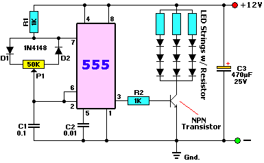
Now being a novice at Electronics i figured if i make 3 of these circuits i could then control each of the 3 colours individually, however i think the "Common-Cathode" is making this not work. As i have made the 3 circuits and connected it to the led on a breadboard (bit messy) and when i adjust any of the 3 Pots, the 3 colours together dim etc, they are not controlling each colour separately but all together on any of the 3 circuits.

I assume this is because the dimming is being done on the common-cathode and therefore instead of dimming each colour, its dimming the whole set of colours in unison.

How if at all can i convert this circuit to dim each of the 3 colours individually please? Without using any PICs etc yet. All i have here right now is 3 555's and a mass of resistors/caps/diodes etc

Thanks and hoping in advance......
 

SgtWookie

Joined Jul 17, 2007
22,230
Well then,
Since they're common cathode, you'll have to play with the anode side ;)

Use the common cathode as your ground (your LED's current return)

You'll still need resistors on the anodes to limit the maximum current to each of the individual R, G, B LED's inside the common module.

Get some PNP transistors on each of the three colors to control them. Emitter to more positive, collector to more negative, base to the 555 output using a 1k or so resistor.
As far as PNP transistors, 2N2907, 2N3906, 2N4402's, 2N4403's would all work.

See the attached - I've only connected the transistor connecting the R LED to the circuit that's shown. The G and B would need their own 555, and connected similarly.
 

Attachments

Last edited:

Thread Starter

Leccy-Lee

Joined Aug 2, 2008
22
Many thanks for your advice, i shall give that a go later indeed..
One thing? Is that for the one colour or three? As theres only one Pot and 3 colours..

Either way i give that a whirl, many thanks
 

SgtWookie

Joined Jul 17, 2007
22,230
Is that for the one colour or three? As theres only one Pot and 3 colours..
Just to simplify things, I only showed the one 555 circuit, and how it connects up to the R LED with a PNP transistor and current limiting resistor.

Now, I DID show the PNP transistors and current limiting resistors for the green and blue portions of the LED, but I didn't show the remaining two timer circuits; as they would be identical to the R portion.

Note that your current limiting resistors will likely need to be different values. This is because they will all have the same current rating (perhaps 20mA or 25mA) but their forward voltage (Vf) will not be the same.

Red LEDs typically have a Vf of from 1.7 to 2.1V.
Green LEDs typically have a Vf of from 2.0V to 3.0V.
Blue LEDs typically have a Vf of from 3.2V to 3.8V.

However, you will get the best results if you measure your actual Vf. This is easily done by using a constant current source and a DMM set to read voltage.

If you do not have a constant current source, you can make one very easily using an LM117/LM317 3-terminal voltage regulator and a single resistor connected between the OUTPUT terminal and the ADJ terminal. A voltage source is supplied to the INPUT terminal, and the constant current is taken from the ADJ terminal. This is documented in National Semiconductor's datasheet for the LM117/LM317. You can download the datasheet from this page:
http://www.national.com/mpf/LM/LM117.html


The formula for the output current is:
Iout = 1.2/R (0.8<= R <=120)
Conversely:
R = 1.2/Iout (0.01 <= Iout <= 1.5)
So, if you want 20mA:
R = 1.2/0.02 = 60 Ohms
62 Ohms is the closest standard value, but frequently they measure slightly less than 62 Ohms. The most important thing is to get the Vf's for close to the LED's max rated current.

Then to calculate the limiting resistors:
Rlimit = (Vsupply - VfLED) / ILED
Note that in your case, you will also need to subtract the collector-emitter saturation voltage from Vsupply in order to arrive at the correct result.
If you are using any of the transistors I suggested, Vce will be about 0.3.
So:
Rlimit = (Vsupply - Vce - VfLED) / ILED
If you measured 1.9v on your red LED, then:
Rlimit = (12 - 0.3 - 1.9) / 0.02 = 9.8/0.02 = 490 Ohms

Here is a page of standard resistor values:
http://www.logwell.com/tech/components/resistor_values.html
If you're using E24 series (which are commonly available) then you could use a 510 Ohm resistor, as a 470 Ohm resistor would allow too much current.

If you don't care about the device having a short lifespan, you could use the lower value resistor.

Let's go with the 510 Ohm resistor for the moment. Figure the power dissipation in the resistor.

We've already determined V(Rlimit) = 9.8V as the interim result in the Rlimit calculation

I(Rlimit) = 9.8/510 = 19.2mA (rounded down)
P(Rlimit) = 9.8 x 19.2mA = 0.1882 Watts (rounded up)
For reliability's sake, we double that.
0.1882 x 2 = 0.3764 Watts.
We will need to use a 1/2 Watt resistor for good reliability. If you don't care about reliability, you could use a 1/4W resistor.
 

Thread Starter

Leccy-Lee

Joined Aug 2, 2008
22
Awesome, you are a star :)
Many thanks for your time and detailed post, i look forward to trying that out this evening.
 

AllVol

Joined Nov 22, 2005
55
Awesome, you are a star :)
Many thanks for your time and detailed post, i look forward to trying that out this evening.
Please note this in your experiment: The led(s) will never grow dim or bright by varying the frequency at which they are switched on and off, and that is all you are doing with the present circuit(s).

Try this, as long as you are trying. Whatever circuit you have on your breadboard, if it successfully lights any LED, substitute the .1 uF cap from pins 2 $ 6, to perhaps a 10uF, or even larger if you wish. Then rotate your pot through its entire range. You should notice that the only change in the output of pin 3 of the 555 is the duration the LED is on and off. The apparent brightness will not change, under normal circumstances.

The equation that governs this is: FREQ = 1.44/(R1 + R2)C1.

Neither voltage nor current is altered by changing the resistance of R2.
 

Wendy

Joined Mar 24, 2008
23,415
Actually the 555 is wired in PWM mode, the diodes steer the current for charge discharge. PWM will make the LEDs vary in intensity just fine.

You're right about one thing though, there is an error in the schematic. SgtWookie has a better schematic here.

Here is the 555 version...


SgtWookie

Joined Jul 17, 2007
22,230
Bill, you need a 10nF cap from pin 5 to ground in your schematic, or it'll have problems in astable mode.

I've actually run simulations on this circuit, and it works just like it should. It gives quite a wide range of PWM.

The circuit I whipped up with the 4093 would work, but you'd have to use one of the spare gates as a buffer. Otherwise, the base of the PNP transistor would simply require too much current for the circuit to both oscillate and drive the base. Either that, or use a voltage follower circuit - and that rather defeats the purpose.

The 4093 is a really handy CMOS IC for low-output oscillators, logic, waveform shaping and the like, but in this case I'd go for a 556 and a 555.
 
Last edited:

Wendy

Joined Mar 24, 2008
23,415
If the power supply is stable, and there isn't other circuitry to dirty up the supply line, the filter cap on pin 5 isn't really needed. There are applications that care, but I don't think an LED dimmer is one of them. I'm definately in the camp of don't use parts unless their actually needed, gets me in trouble sometimes, but not often.

I showed the 555 version. I like the minimum parts count, and the fact it is extremely wide range (more so than the original schematic).

I'll tell you about the transistorized SCR I fought sometime.

The OP project is interesting in that I was thinking of doing something similar, only with variable power supplies into a Common Anode RGB diode I have bought for the purpose. Either way works, the power supply method will go all the way to no light though. I suspect we are thinking along the same lines, to see what the real spectum of the device is.

If you are under 100ma the transistor driver isn't really needed, the 555 will source up to 200ma.
 
Last edited:

SgtWookie

Joined Jul 17, 2007
22,230
If the power supply is stable, and there isn't other circuitry to dirty up the supply line, the filter cap on pin 5 isn't really needed. There are applications that care, but I don't think an LED dimmer is one of them. I'm definately in the camp of don't use parts unless their actually needed, gets me in trouble sometimes, but not often.
True, but... you don't show a cap across the supply pin and ground, either! gotta use either the 10nF on pin 5, or a BIG cap across Vcc & ground. I figure the 10nF is cheap insurance ;)

I showed the 555 version. I like the minimum parts count, and the fact it is extremely wide range (more so than the original schematic).
Yeah, that 1k resistor in the circuit the OP posted limits the ends a bit, but for that circuit, it has to be present.

I'll tell you about the transistorized SCR I fought sometime.
Couldn't turn it off, eh? ;)

The OP project is interesting in that I was thinking of doing something similar, only with variable power supplies into a Common Anode RGB diode I have bought for the purpose. Either way works, the power supply method will go all the way to no light though. I suspect we are thinking along the same lines, to see what the real spectum of the device is.
You can do the same thing with a single 8-pin $0.75 microcontroller. I have a board sitting here all wired up with an RGB LED, just waiting for me to finish the coding for a PIC12F675.

If you are under 100ma the transistor driver isn't really needed, the 555 will source up to 200ma.
Quite true for the bipolar and CMOS 555's, but the low powered 555's would choke on it. Not knowing for certain which 555 our OP had, I simply made the fewest mods possible, keeping it as similar to the original design as I could.

Once our OP reports back as to whether they got it working with the existing schematic, they can try removing the PNP driver, the 1k resistor, and connecting the Rlimit directly to pin 3 of the respective 555 timer and see if it works the same (which it should, if it's a bipolar 555).
 

Thread Starter

Leccy-Lee

Joined Aug 2, 2008
22
Quick Update:

Got it dimming fine now on all 3 colours thanks.
I didn't get any PNP transistors as i had none handy, so i just moved the LEDs from the collector line of the NPN to the emitter line. As seeing your diagram made me realise how damn simple my original post and error was! Doh..
(i will do a new diagram later)

Will now go back over you guys posts and see what improvements i can do to it..
Thanks for all advice, for a newcomer to this site a massive thumb-up!
:)
 

Thread Starter

Leccy-Lee

Joined Aug 2, 2008
22
Further Update:

Going on all your posts and Bills theory to remove unneeded parts, i have now removed the transistor driver and its resistor (pin3 1k) and feeding the LEDs direct from pin3. Also following Bills post i have removed the filter cap from pin5 without any problems also.

So i have just halved the components almost :) and my breadboard is looking tidier as a result!

Now, as i think you said the 1k resistor in the diode section is limiting the dimming to about 5%-95% dimming and therefore there is no "off" position. Not being yet brave enough to remove that 1k resistor how can i now improve that dimming to have an "off" position (0%).

Also i dont have a constant-current source or L117 yet so i am using safe values for now, but i will get one sorted to get more exact values soon.

Thanks for help, i am really enjoying this return to electronics and playing around. Haven't touched a resistor or component since college 15yrs ago and that was only very basic electronics.

Now the quest for 0%-> dimming.
 

Wendy

Joined Mar 24, 2008
23,415
Here's how I would do it...


Basically I'm assuming the 12VDC is regulated, the design is set up for around 20ma max. The transistor is major overkill, I just picked the first Darlington that was close. The circuit is wired as a constant current configuration. You can measure the current by measuring the voltage across the 470Ω, then dividing by 470.

I drew this with my PaintCAD package, you can find it on my blog at this side (look for the blue number next to blog entries).

***********

I forgot you were talking common cathode, so I redrew the schematic to match.

 
Last edited:

Thread Starter

Leccy-Lee

Joined Aug 2, 2008
22
Well thought i'd update this..
I never changed the design much after previous posts, as i will now start working on the more serious version with PIC's etc. But its been fun returning to Electronics and practicing soldering etc :)

Heres my final prototype with the 555 Timers for PWM. I might remod it to some 1w hi-power LED's next week when they arrive from overseas.


SgtWookie

Joined Jul 17, 2007
22,230
Glad to see you got it going :)

Try a PICkit 1 and a couple of 12F675's. I have one sitting here that's flashing a dozen LED's in various sequences. I have another very small protoboard with an RGB LED waiting for me to plug in a programmed 12F675 to drive it.

You can get an interesting kit from Big Clive.
http://www.bigclive.com/
http://www.bigclive.com/rgbcont.htm

His site is well worth dabbling around in, if only for his offbeat sense of humor. :)
 

Pfrogs

Joined Oct 26, 2008
1
Hi Leccy-Lee,
I have been looking for a rgb colour mixer that doesn't require a microprocessor, just 3 pots to dim each colour separetly. That's when I came across with this post. Well, I am not very experienced in electronics, but if you could send me a diagram of your final prototype with the 555 Timers for PWM circuit I think that would help me understand how it is done and adapt it to my project.
Also I have a question. I want to control 25 RGB LEDs (4pin, common cathode) that will be connected in parallel, so if I run them in 20mA each, that would mean I would have a 500mA passing throw the 555, right? Is there any 555 available that can handle such current? How could I solve this problem?
Thank you very much for your attention.
Looking forward for your reply ;)
Best regards!
 
Top